Laser emitting device and cutting machine with the same
A laser emitting and adjusting device technology, which is applied in the direction of sawing machine accessories, optics, optical components, etc., can solve the problems of dim and blurred light spots, damage to the operator's eyes, and inability of the operator to see clearly, so as to facilitate observation and improve Machining accuracy and effect of improving efficiency
- Summary
- Abstract
- Description
- Claims
- Application Information
AI Technical Summary
Problems solved by technology
Method used
Image

Examples
Embodiment Construction
[0033] The present invention will be further described below in conjunction with the accompanying drawings and preferred embodiments.
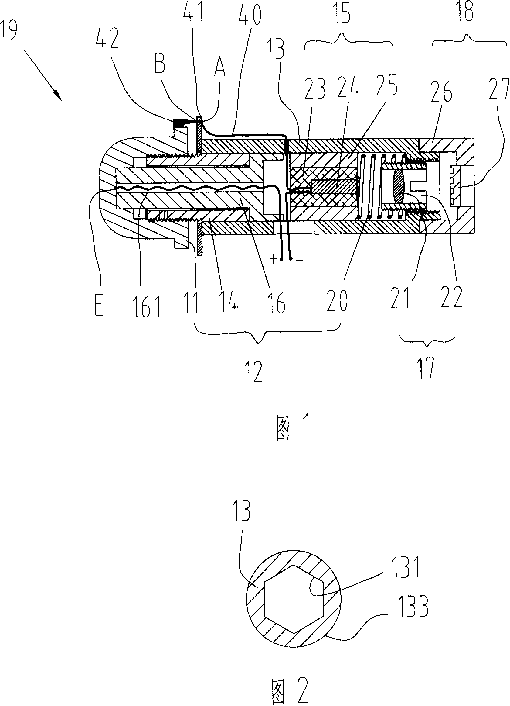
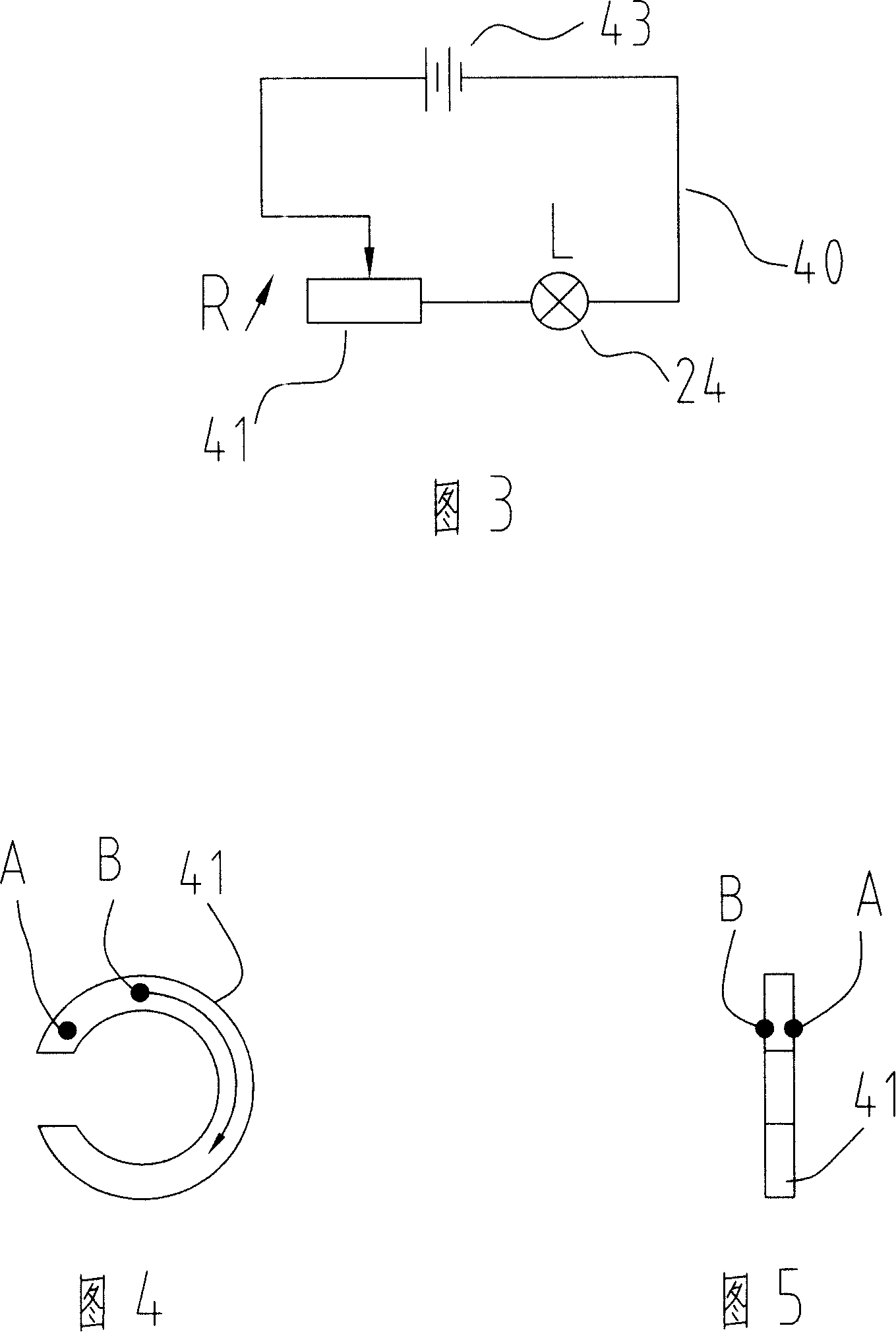
[0034] As can be seen from the cross-sectional view of the laser emitting device shown in Figure 1 along its axial direction, the laser emitting device 19 includes a housing 13, which is provided with a light-emitting assembly 15, a light-condensing assembly 17, and a light-scattering assembly 18, and the light-emitting assembly 15 It includes a light source 24 and a circuit 40 connected to the light source 24 , the light collecting assembly 17 is fixedly connected to the casing 13 , and the light emitting assembly 15 is movably arranged in the casing 13 .
[0035] As shown in FIG. 1, the laser emitting device 19 also includes an adjusting device 12 for adjusting the position of the light-emitting component 15 relative to the housing 13. The adjusting device 12 includes a push rod sleeve 14, a push rod 16, a knob 11 and an elastic element 20. ...
PUM
 Abstract
Description
Claims
Application Information
 - Generate Ideas
- Intellectual Property
- Life Sciences
- Materials
- Tech Scout
- Unparalleled Data Quality
- Higher Quality Content
- 60% Fewer Hallucinations
Browse by: Latest US Patents, China's latest patents, Technical Efficacy Thesaurus, Application Domain, Technology Topic, Popular Technical Reports.
© 2025 PatSnap. All rights reserved.Legal|Privacy policy|Modern Slavery Act Transparency Statement|Sitemap|About US| Contact US: help@patsnap.com