

Vertical rolling machine
A winder, vertical technology, applied in the direction of conveying filamentous materials, thin material handling, transportation and packaging, etc., can solve the problems of increasing unloading time, troublesome operation, reducing production efficiency, etc., to reduce labor intensity, The unloading work is simple and the effect of improving production efficiency
- Summary
- Abstract
- Description
- Claims
- Application Information
AI Technical Summary
Problems solved by technology
Method used
Image

Examples
Embodiment Construction
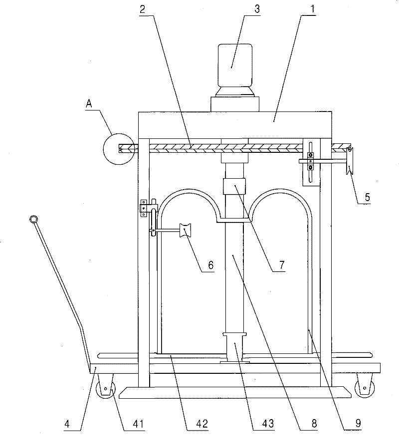
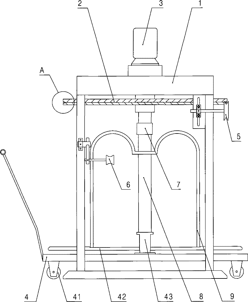
[0012] Specific embodiments of the present invention will be described in detail below in conjunction with the accompanying drawings.
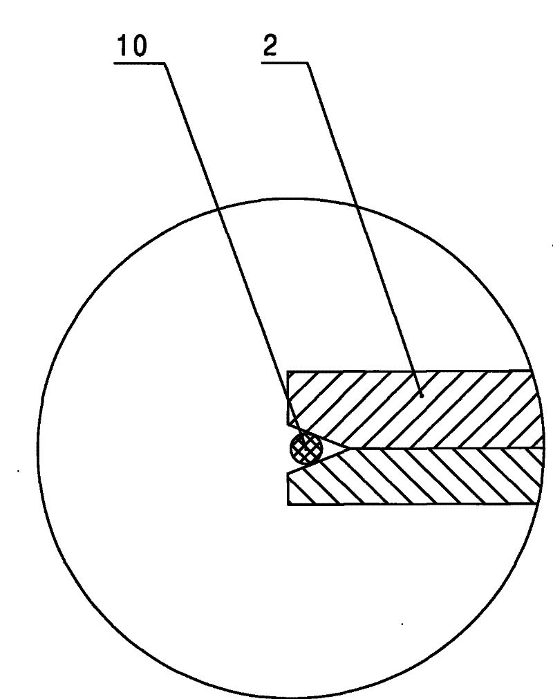
[0013] Such as figure 1 As shown, the vertical winder of the present invention includes: a frame 1, the top of the frame 1 is provided with an inverted driving device 3 mainly composed of a torque motor and a reducer, and the output shaft of the driving device 3 is a deceleration The output shaft of the machine is provided with a looper coupling 7, and the upper part of the frame 1 is movably provided with a traction disc 2 composed of upper and lower discs, and the circumferential surface of the traction disc 2 is provided with The "V"-shaped clamping groove enables the traction disc 2 to stably clamp various wires or pipes. The frame 1 is provided with an introduction wheel 5 for introducing wires or pipes next to the clamping groove. On the traction disc 2 The bottom of the reel 9 and the lead-out wheel 6 matched with the reel 9 are arrang...
PUM
 Abstract
Description
Claims
Application Information