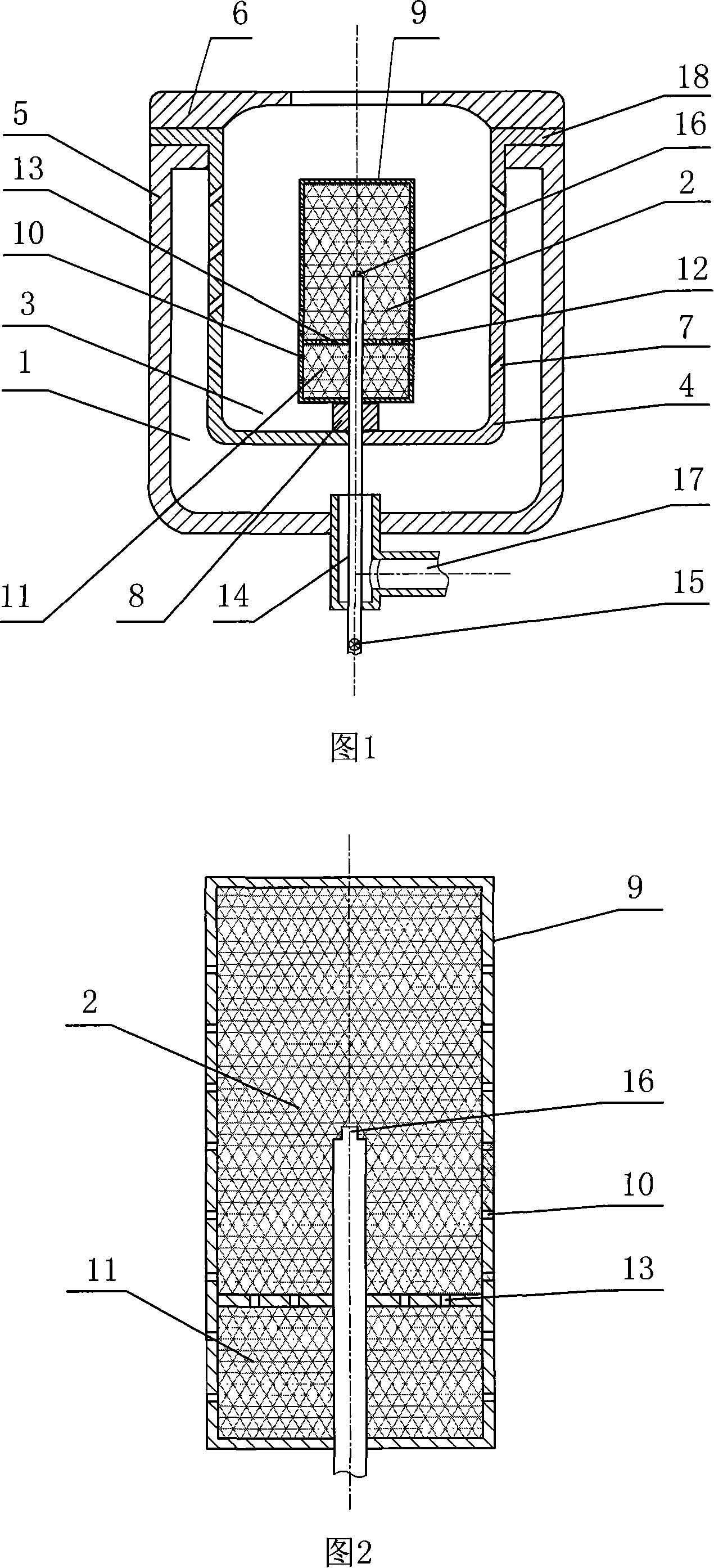
Highly effective liquid fuel evaporation combustion device

A liquid fuel and combustion device technology, applied in the direction of evaporating liquid fuel burners, gas fuel burners, burners, etc., can solve the problems of inconvenient maintenance, low fuel vaporization temperature, low combustion efficiency and thermal efficiency, etc.

Inactive Publication Date: 2008-03-26
傅学正
View PDF1 Cites 9 Cited by
  • Summary
  • Abstract
  • Description
  • Claims
  • Application Information

AI Technical Summary

Problems solved by technology

Its shortcomings are: (1) the vaporization capacity of the vaporization tank is weak; (2) the fuel vaporization temperature is low, the combustion efficiency and thermal efficiency are low; (3) the fuel delivery pipe is easy to leak, and maintenance is inconvenient

Method used


Image

  • Highly effective liquid fuel evaporation combustion device

Examples


Embodiment Construction

[0021] Referring to the accompanying drawings, a high-efficiency liquid fuel vaporization combustion device includes a gas chamber 1, a vaporization chamber 2 and a combustion chamber 3. There is a combustion cylinder 4 between the gas chamber 1 and the combustion chamber 3, and its upper edge extends horizontally and radially Form an annular flange 18; in order to make the combustion flame more concentrated, the top of the annular flange 18 is movably connected to the fire cover 6, and the bottom of the annular flange 18 is connected to the gas chamber cylinder 5, and the gas chamber cylinder 5 and the combustion cylinder The area surrounded by 4 is the air chamber 1, and the bottom surface of the air chamber cylinder 5 is connected to a fan through the ventilation pipe 17. In order to facilitate maintenance, the vaporized fuel can be mixed with the air faster and more fully, and the combustion is more complete. The ventilation pipe 17 connected to the bottom surface of the ga...


PUM


Abstract

This invention is a high efficiency liquid fuel vaporizing combustion device. It includes air chamber, vaporizing chamber and combustion chamber. There is combustion barrel is arranged between air chamber and combustion chamber. Its superior edge extends along horizontal radial direction and forms a ring shaped flange. The lower part of flange connects to air chamber barrel body, the bottom of which connects to air pipe. The radial wall of combustion barrel is arranged with air hole. The center of combustion barrel bottom has vaporizing tank, the center of which is arranged with fuel conveying pipe and nozzle. The internal wall of vaporizing tank has division plate, on which has the communicating hole communicating to the vaporizing chamber. The radial wall of vaporizing tank has fuel releasing hole. There is supporting gasket between vaporizing tank and combustion barrel bottom. Heat transferring medium is arranged inside of vaporizing chamber. This invention is adequate for equipment coordination such as boiler, kitchen range and air conditioner.

Description

technical field [0001] The invention relates to a combustion device, in particular to a high-efficiency liquid fuel vaporization combustion device. Background technique [0002] The present invention is an improvement on the applicant's previous patent application number: "200720063602.7 liquid fuel vaporization burner". A liquid fuel vaporization burner in the prior patent application includes a gas chamber, a vaporization chamber, a combustion chamber, a combustion cylinder, a simplified body of the gas chamber, a tight fire cover, an air hole, a support pad, a vaporization tank, a fuel release hole, a partition, and a communication hole , Fuel delivery pipe, ventilation pipe, nozzle, and vaporization tank are divided into multiple vaporization chambers by partitions, the fuel delivery pipe is arranged horizontally, and the ventilation pipe is arranged vertically. Its disadvantages are: (1) the vaporization capacity of the vaporization tank is weak; (2) the fuel vaporizat...

Claims


Application Information

Patent Timeline
Patent Type & Authority Applications(China)
IPC IPC(8): F23D5/00F23D11/22F23D5/04F23D11/44F23D14/22
Inventor 傅学正
Owner 傅学正
Why Eureka
Try Eureka