

Backlight module
A technology for backlight components and light sources, applied in optics, nonlinear optics, identification devices, etc., can solve problems such as excessive leakage current and electric power consumption, and achieve the effect of improving safety and improving parasitic capacitance.
Image

Examples
no. 1 example
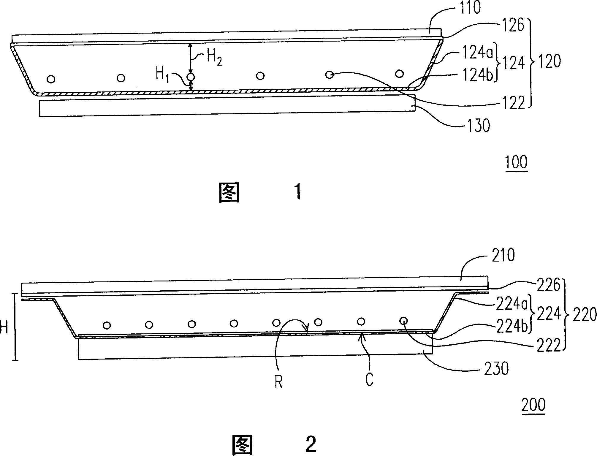
[0042]FIG. 2 is a schematic cross-sectional view of a liquid crystal display according to a first embodiment of the present invention. Please refer to FIG. 2 , the liquid crystal display 200 of the present invention includes a liquid crystal display panel 210 and a backlight assembly 220 . Wherein, the liquid crystal display panel 210 is disposed above the backlight assembly 220 , and the backlight assembly 220 is suitable for providing a side light source to the liquid crystal display panel 210 so that the liquid crystal display panel 210 can achieve display purposes. Generally speaking, an inverter 230 can be disposed next to the backlight assembly 220 , and the inverter 230 is suitable for converting DC power into AC power required to light the backlight assembly 220 .
[0043] Please refer to FIG. 2 again, the backlight assembly 220 includes a plurality of light sources 222 , a frame 224 and an optical film 226 . Wherein, the frame 224 has a plurality of side surfaces 224...
no. 2 example
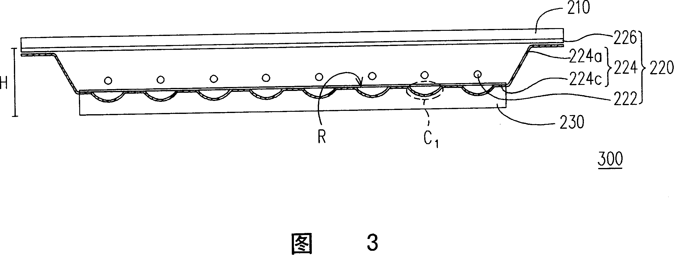
[0050] FIG. 3 is a schematic cross-sectional view of a liquid crystal display according to a second embodiment of the present invention. Please refer to FIG. 3 , the liquid crystal display 300 of the second embodiment of the present invention is very similar to the first embodiment, and the main difference between the two is that: the bottom surface 224c of the backlight assembly 220 of this embodiment has a plurality of depressions C1, and separated from each other. The light sources 222 are respectively fixed in the frame 224 corresponding to the recesses C1. The above-mentioned concave portion C1 can be designed as a concave surface, such as an arc surface, and the light source 222 can be disposed at the center of the concave surface. In other words, this embodiment improves the prior art by forming the recessed portion C1. The CCFL tube 122 (as shown in FIG. 1 ) and the metal back plate 124b (as shown in FIG. 1 ) are too close to each other to cause problems during lighti...
no. 3 example
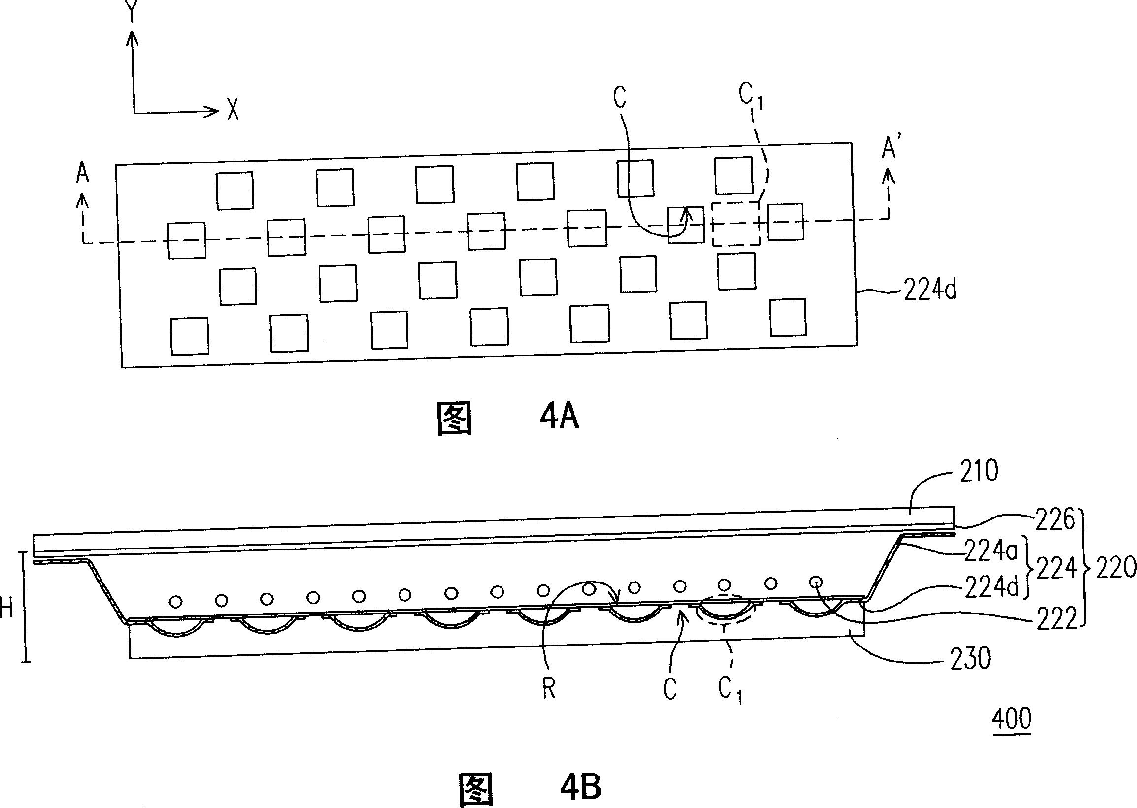
[0052] FIG. 4A is a bottom rear view of a liquid crystal display according to a third embodiment of the present invention, and FIG. 4B is a schematic cross-sectional view along line A-A' in FIG. 4A. Please refer to FIG. 4A and FIG. 4B. In the example of the liquid crystal display 400 of the embodiment of the present invention, a plurality of depressions C1 and through holes C are simultaneously formed on the bottom surface 224d, and the depressions C1 and the through holes C are formed along a first direction X. are alternately arranged, and the recessed portions C1 and the through holes C are also arranged alternately along a second direction Y. Wherein, the first direction X and the second direction Y may be perpendicular to each other.
PUM
 Abstract
Description
Claims
Application Information
- IPC
- G02F1/13357; G02F1/1333; G09F9/35; G02F1/1335
- Inventors
- 林文郁