Shaft current control brush ring assembly

A technology of brush device and brush ring, which is applied in the direction of electromechanical devices, static electricity, electrical components, etc., can solve the problem of increasing shaft induced current, etc., and achieve the effect of improving grounding performance and improving conductivity

Active Publication Date: 2008-03-26
ILLINOIS TOOL WORKS INC
View PDF1 Cites 11 Cited by
  • Summary
  • Abstract
  • Description
  • Claims
  • Application Information

AI Technical Summary

Problems solved by technology

The disadvantage of using an AC motor with a variable speed drive is the high common mode voltage (CMV) generated by the variable speed drive, which increases the shaft induced current
Brush vibration, whatever its cause, can lead to unwanted sparks

Method used


Image

  • Shaft current control brush ring assembly
  • Shaft current control brush ring assembly

Examples


Embodiment Construction

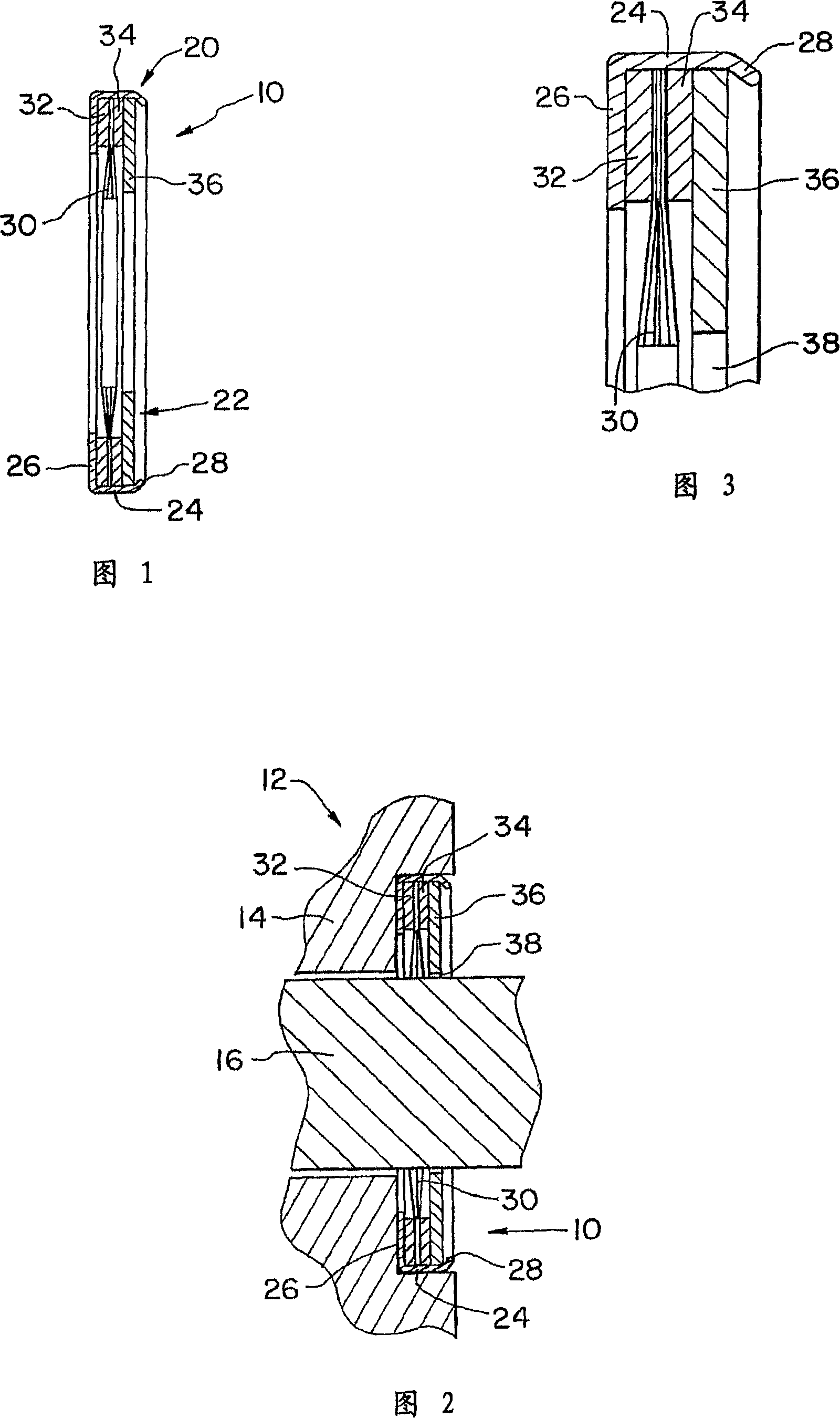
[0025] Referring now more particularly to the drawings and to FIG. 1 in particular, reference numeral 10 indicates a shaft current control brush ring arrangement according to the invention. The brush ring arrangement 10 is mounted on the motor 12 ( FIG. 2 ) and in particular on the faceplate 14 of the motor 12 for dissipating electrical charge that may accumulate on the shaft 16 of the motor 12 . It should be understood that the brush ring assembly 10 may be provided in a variety of different sizes for use in different types of electric machines and on shafts 16 of different diameters.

[0026] The brush ring assembly 10 is generally annular, surrounding an axis 16 . The brush ring assembly 10 is fixed to the panel 14 and is operably mounted between the spindle 16 and the panel 14 . The brush ring arrangement 10 operates continuously to remove charge that builds up on the motor shaft 16 during operation of the motor 12 by transferring the charge from the main shaft 16 to the ...


PUM


Abstract

A shaft current control brush ring device includes a cup and a brush ring device fixed in the cup. The cup is fixed in a recess formed on the panel of the motor in an interference fit manner or attached to the panel by means of clips. The oil deflector ring can be attached to the brush ring assembly.

Description

[0001] Cross-references to related applications [0002] This application claims priority to U.S. Provisional Application No. 60 / 673,308, filed April 20, 2005, and is a continuation-in-part of co-pending U.S. Patent No. 10 / 877,112, filed June 25, 2004, above Patent claiming priority to U.S. Patent Application No. 60 / 508,949, filed October 6, 2003, and U.S. Patent Application No. 60 / 508,950, also filed October 6, 2003, and is November 2003 A continuation-in-part of co-pending US Patent No. 10 / 714,295 filed on the 14th, which claims priority to provisional application US Patent No. 60 / 455,301 filed on March 17, 2003. technical field [0003] The present invention generally relates to grounding devices for controlling shaft currents generated by AC variable speed motors or DC motors, generators and other rotating shafts, and more particularly, to non-contact grounding devices. Background technique [0004] Shaft-induced currents are generated in electric motors, typically thre...

Claims


Application Information

Patent Timeline
Patent Type & Authority Applications(China)
IPC IPC(8): H02K11/00H05F3/02
Inventor 希阳·W.·欧亚当·H.·维尔韦瑟
Owner ILLINOIS TOOL WORKS INC
Why Eureka
Try Eureka