Rotating shaft used for motor

A technology for electric motors and rotating shafts, applied in the direction of electric components, shafts, electrical components, etc., can solve problems such as poor heat dissipation, shortened service life of motors, and reduced working performance of motors

Pending Publication Date: 2018-02-02
方大电机股份有限公司
View PDF0 Cites 0 Cited by
  • Summary
  • Abstract
  • Description
  • Claims
  • Application Information

AI Technical Summary

Problems solved by technology

[0002] The ventilation and heat dissipation effect of the existing motor shaft is poor, and the motor will generate high temperature inside the motor and the shaf

Method used


Image

  • Rotating shaft used for motor
  • Rotating shaft used for motor
  • Rotating shaft used for motor

Examples


Embodiment Construction

[0011] The following descriptions are only preferred embodiments of the present invention, and do not limit the protection scope of the present invention. The present invention will be further described below in conjunction with the accompanying drawings and embodiments.

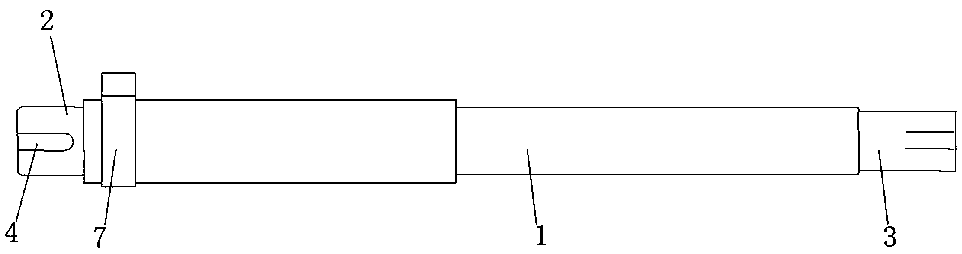
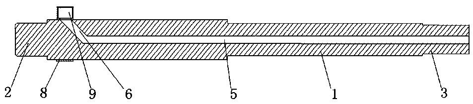
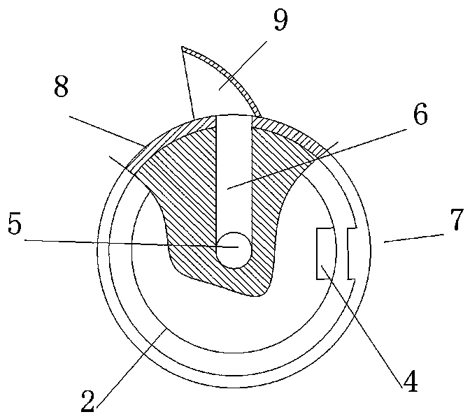
[0012] Examples, see Figure 1 to Figure 3 As shown: a rotating shaft for a motor, including a main shaft body 1, the two ends of the main shaft body 1 are respectively the installation end 2 and the fan connection end 3, and the installation end 2 and the fan connection end 3 are respectively provided with key grooves 4, The axis position of the main shaft body 1 is provided with an exhaust duct hole 5, the right port of the exhaust duct hole 5 is exposed at the fan connection end 3, and the main shaft body 1 adjacent to the installation end 2 is provided with an exhaust duct hole. The left port of 5 communicates with the air inlet channel 6 , and the main shaft body 1 is provided with an air induction devi...


PUM


Abstract

The invention discloses a rotating shaft for a motor, which comprises a main shaft body, and the two ends of the main shaft body are respectively an installation end and a fan connection end, and the installation end and the fan connection end are respectively provided with key grooves. The shaft center of the main shaft is provided with an exhaust duct hole, the right port of the exhaust duct hole is exposed at the fan connection end, and the main shaft body adjacent to the installation end is provided with an air inlet channel communicating with the left port of the exhaust duct hole. The main shaft body is provided with an air induction device corresponding to the channel opening of the air inlet channel. The invention has the characteristics of fast heat dissipation speed and is beneficial to reduce the usage amount of the iron core silicon steel sheet of the motor and the magnet wire of the motor winding.

Description

technical field [0001] The invention belongs to the technical field of motor shafts, in particular to a rotating shaft for a motor. Background technique [0002] Existing motor shafts have poor ventilation and heat dissipation effects, and long-term operation of the motor will cause high temperature inside the motor and the shaft, which will cause failures, reduce the working performance of the motor, and shorten the service life of the motor. Contents of the invention [0003] The object of the present invention is to address the shortcomings of the above-mentioned prior art, and to provide a rotating shaft for a motor, which has the characteristics of fast heat dissipation and is beneficial to reduce the consumption of the silicon steel sheet of the motor core and the magnet wire of the motor winding. [0004] In order to achieve the above object, the technical solution adopted in the present invention is: a rotating shaft for a motor, including a main shaft body, the tw...

Claims


Application Information

Patent Timeline
IPC IPC(8): H02K7/00F16C3/02
CPCH02K7/003F16C3/02
Inventor 罗钦友
Owner 方大电机股份有限公司
Why Eureka
Try Eureka