Common-mode voltage suppression method for wind power dual-winding generator system

A wind turbine, common-mode voltage technology, applied in wind power generation, circuit devices, electrical components, etc., can solve problems affecting the insulation life of motor windings, system zero-sequence current loss, and damage to motor winding insulation, and achieve great economic value. and prospects, insulation life extension, the effect of avoiding failure

Active Publication Date: 2022-01-25
YUANJIAN WIND POWER JIANGYINENVISION ENERGY CO LTD
View PDF0 Cites 0 Cited by
  • Summary
  • Abstract
  • Description
  • Claims
  • Application Information

AI Technical Summary

Problems solved by technology

[0005] For megawatt-scale wind turbine and converter systems, the common mode voltage of the system is high due to the use of voltage pulse width modulation (PWM), causing excessive shaft current, which is likely to cause electrical corrosion damage to the bearings; Cause damage to the motor winding insulation, affecting the life and failure rate of the motor winding insulation
Excessive common-mode voltage may also cause electrical system electromagnetic interference (EMI) and electromagnetic compatibility (EMC) problems; if there is a large amount of zero-sequence current flowing, it will also cause unnecessary system zero-sequence current loss

Method used

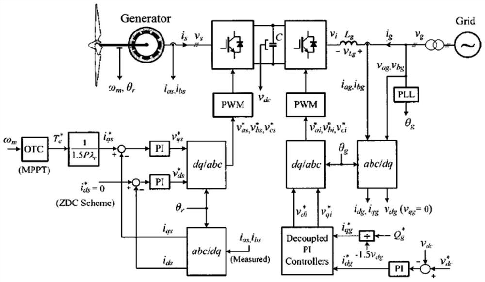

Image

  • Common-mode voltage suppression method for wind power dual-winding generator system
  • Common-mode voltage suppression method for wind power dual-winding generator system
  • Common-mode voltage suppression method for wind power dual-winding generator system

Examples


Embodiment Construction

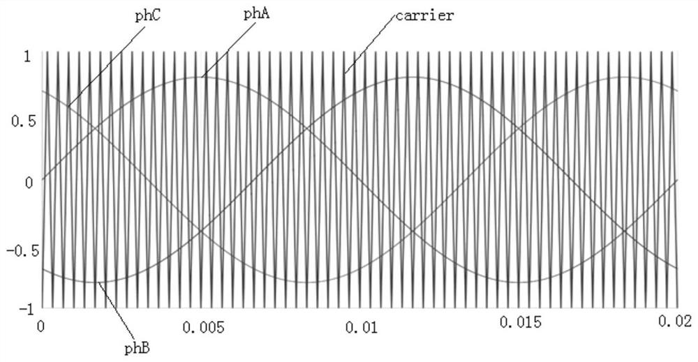
[0016] The frequency of the carrier signal defines the switching frequency of the converter, the amplitude of the carrier is a fixed value, and there is no requirement for the initial phase of the carrier. There will be no problem with PWM in a single converter. However, in a system of multiple converters, due to the interaction, the initial phase of the carrier wave in the PWM module will have a certain impact on system performance, especially for wind power systems. In the structure of multi-winding motor and converter system. Therefore, no related documents and patents can be found on how to use this effect to reduce the common-mode voltage.

[0017] The carrier frequency and phase of the grid-side converter and the machine-side converter connected to the same set of windings do not need to be the same, but the corresponding two grid-side converters and two machine-side converters connected by two sets of windings The frequency and phase need to satisfy the relationship th...


PUM


Abstract

The invention relates to a common-mode voltage suppression method for a wind power generation double-winding generator system. Each set of windings of a double-winding wind power generator is connected to a machine-side converter, and the frequency-changing AC power is converted into DC power, and then passed through the grid-side converter. The DC power is converted into AC power with a fixed frequency by a transformer, and finally it is boosted and transmitted to the power grid through a transformer. The double-winding wind turbine has two sets of windings, and the four converters use voltage pulse width modulation PWM signals to control the converters. , through two machine-side converters to control the phase inversion of the carrier phase used to generate the PWM signal; two grid-side converters to control the phase inversion of the carrier phase used to generate the PWM signal to reduce the common mode voltage of the system. This method can reduce the common-mode voltage of the system, prolong the insulation life of the motor windings, and reduce the harm of electromagnetic interference in the system without changing the structure of the motor and any other hardware for the large-scale motors and converters that have been manufactured. EMC standard requirements.

Description

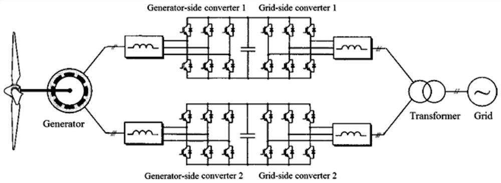
technical field [0001] The invention relates to a motor control technology, in particular to a common-mode voltage suppression method for a wind power generation double-winding generator system. Background technique [0002] With the development of wind power generation technology, the power of a single wind turbine is getting bigger and bigger, and the current requirement is increasing proportionally at the same voltage level. By designing a generator with double windings, the average current distribution can be kept within the allowable capacity under the condition of power increase. [0003] A typical dual-winding wind turbine control system such as figure 1 As shown in Fig. 1, each set of windings is connected with two converters with similar hardware structure and different software functions, which are called generator-side converter and grid-side converter respectively. First, the wind turbine captures wind energy through the blades and converts it into rotating mec...

Claims


Application Information

Patent Timeline
Patent Type & Authority Patents(China)
IPC IPC(8): H02J3/38H02M5/458H02M1/12H02M1/44
CPCH02J3/386H02M1/12H02M1/44H02M5/4585H02M1/123Y02E10/76
Inventor 刘勇邓恒库尔特·安徒生刘佳
Owner YUANJIAN WIND POWER JIANGYINENVISION ENERGY CO LTD
Why Eureka
Try Eureka