Window roller blind

A rolling shutter and rolling spring technology, used in door/window protection devices, transportation and packaging, building components, etc., can solve the problem of not blocking the noise of the rolling shaft well enough, and achieve the effect of increasing the weight

Inactive Publication Date: 2008-04-02
BOS
View PDF1 Cites 4 Cited by
  • Summary
  • Abstract
  • Description
  • Claims
  • Application Information

AI Technical Summary

Problems solved by technology

[0004] What is seen as a disadvantage in the prior art is that the noise generated inside the reel, especially by vibrations, is not well damped

Method used


Image

  • Window roller blind

Examples


Embodiment Construction

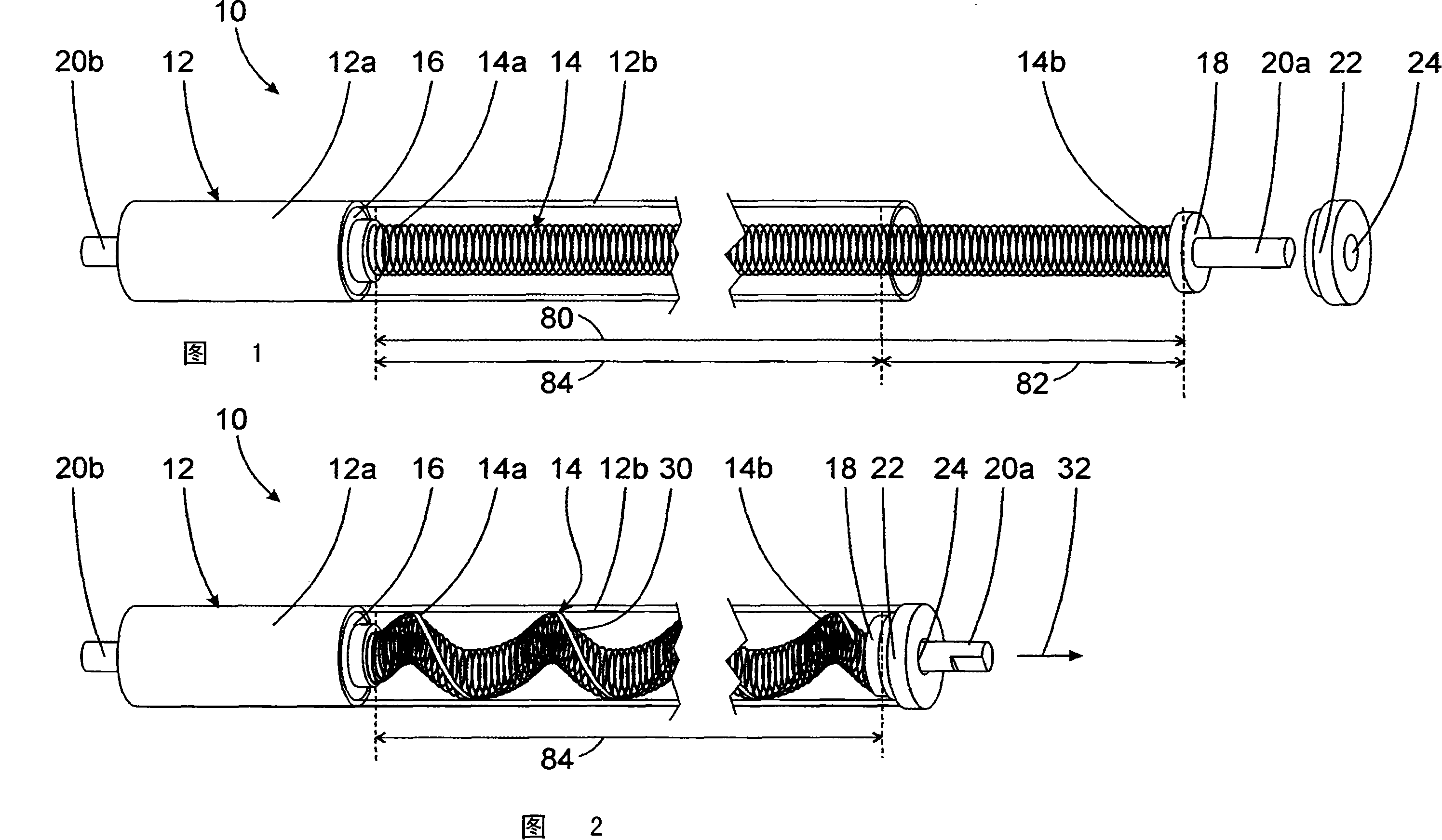
[0021] FIG. 1 shows a roller blind arrangement 10 , the main components of which are a roller shaft 12 and a roller spring 14 . The reel 12 is designed as a hollow tube, which is shown partially transparent in the illustrated embodiment for better understanding. The spool is used to accommodate the planar article in rolled form, where the planar article is not shown in the figures. A spring holder 16 is arranged in the reel 12 , which is connected to the reel 12 in a relatively non-rotatable manner on one side and to the first end 14 a of the coil spring 14 in a relatively non-rotatable manner. The spring holder 16 divides the spool into a springless section 12a and a spring containing section 12b.

[0022] In the unclamped state, the coil spring 14 has a length 80 which is longer than a length 84 of the spring receiving section 12 b by a length difference 82 . Arranged at the second end of the coil spring 14 is a fastening section 18 which is connected to the second end 14 ...


PUM


Abstract

The present invention relates to a roller blind arrangement for vehicle which comprises: a hollow tubular winding shaft for winding and holding a flexible flat object, and a winding spring which is placed in a winding shaft spring receptable section and constructs a spiral spring. The first end of the winding spring is not rotationally fixed to the winding shaft, the second end of the winding spring is fixed to a holding section not rotatable about a main axis of the winding shaft. The winding spring has an outer diameter smaller than the inner diameter of the spring receptacle section. The radial mobility of the winding spring transversal to the main extending direction of the winding shaft is delimited by an inner wall of the spring receptacle section. According to the present invention, The winding spring, in a relaxed state, is longer than the spring receptacle section such that the winding spring, in a compressed and untwisted state in which the winding spring is compressed approximately to the length of the spring receptacle section, bears substantially over the entire length against the inner wall of the spring receptacle section.

Description

technical field [0001] The invention relates to a roller blind device, in particular for use in motor vehicles, which has a hollow tubular reel extending in the main direction of extension for rolling up a pull-out flexible planar article and an insert Coil spring in the spring housing section of the reel and configured as a helical spring, wherein the first end of the coil spring is non-rotatably connected to the reel and the second end of the coil spring is rotatable relative to the reel around the main axis of the reel The ground-shaped fixed section is connected in a rotationally fixed manner, the coil spring has an outer diameter smaller than the inner diameter of the spring receiving section, and the radial mobility of the coil spring transverse to the main direction of extension of the coil spring is only performed by the inner wall of the spring receiving section limit. Background technique [0002] Such roller blind devices are known from the prior art. In this ro...

Claims


Application Information

Patent Timeline
Patent Type & Authority Applications(China)
IPC IPC(8): E06B9/44E06B9/60
CPCE06B9/42B60J1/2063E06B9/60E06B9/40
Inventor M·汉森
Owner BOS
Why Eureka
Try Eureka