
Seamless safe light curtain designed by cylindrical mirror

A technology of safety light curtains and cylindrical mirrors, applied in the field of seamless safety light curtains, can solve the problems that safety light curtains cannot be detected, easily cause wrong judgments, and reduce light energy, and achieve the elimination of detection blind spots, simple structure, and easy detection sensitive effect

Inactive Publication Date: 2008-04-02
UNIV OF SHANGHAI FOR SCI & TECH
View PDF0 Cites 11 Cited by
  • Summary
  • Abstract
  • Description
  • Claims
  • Application Information

AI Technical Summary

Problems solved by technology

However, due to the spacing between the diodes, there is also a gap between the beams emitted by the diodes, so that the safety light curtain actually has a blind area that cannot be detected.
Moreover, when the divergent beam is used at a long distance, the received light energy is greatly reduced, which is easy to cause misjudgment. Measures must be taken to control the divergence angle of the beam within the allowable range

Method used


Image

  • Seamless safe light curtain designed by cylindrical mirror
  • Seamless safe light curtain designed by cylindrical mirror

Examples


Embodiment 1

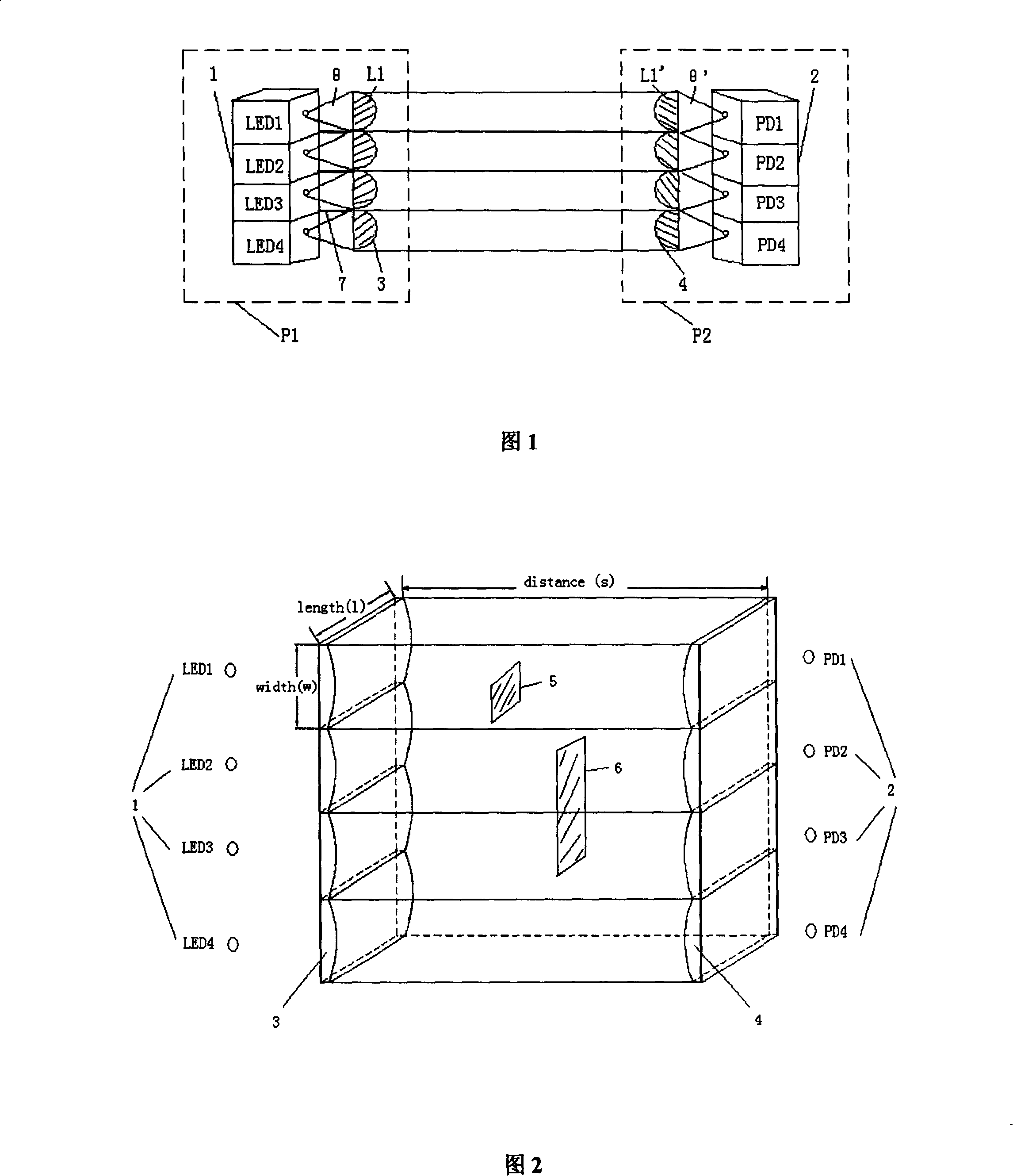
[0016] In this embodiment, the sending and receiving arrays are selected to be composed of 4 sending tubes and receiving tubes. The design principle of the cylindrical mirror is illustrated through this embodiment. In each infrared emitting tube 1 (with LED 1 as an example) and infrared receiving tube 2 (take PD 1 Take as an example) a cylindrical mirror 3 (L 1 ), cylindrical mirror 4 at the receiving end (L 1 ’), so that the transmitting / receiving tubes are located at L 1 , L 1 ’ focus, the LED 1 The emitted large-angle divergent light is approximated as a parallel beam by a cylindrical mirror, which can be transmitted over a long distance. At the receiving end, the widened beam is focused on the photosensitive surface of the infrared receiving tube by a cylindrical mirror. The cylindrical mirrors at the entire transmitting end are closely arranged without gaps, so that the light emitted by the LED array becomes a closely connected parallel light curtain after passing t...

Embodiment 2

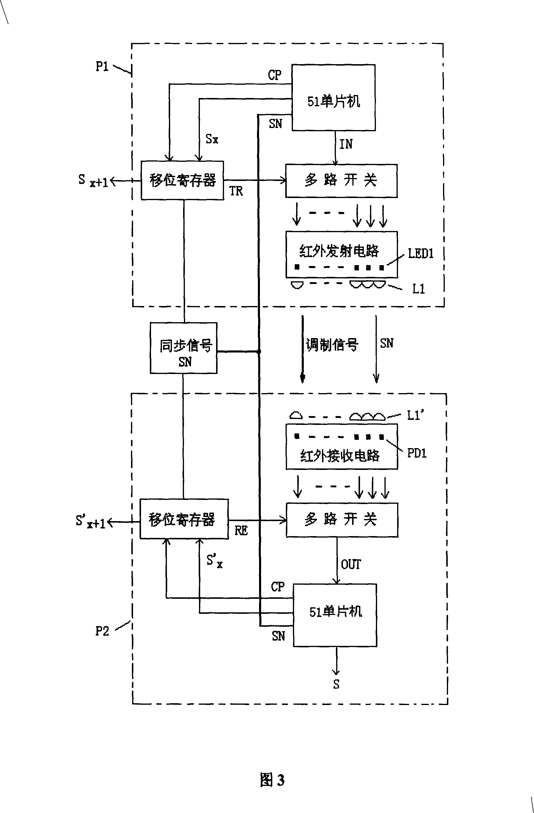
[0026] In this embodiment, a sending / receiving array is composed of a plurality of sending tubes and receiving tubes, and the multiple sending / receiving arrays are cascaded through gating signals; the light curtain is composed of an infrared emitting part P1 and an infrared receiving part P2 placed face to face. The transmitting part is an infrared light-emitting diode LED array and its control circuit, and the receiving end is an infrared receiving tube PD array and its control circuit; each light-emitting diode corresponds to an infrared receiving tube on the opposite side, and is installed on the same straight line. Coaxially place cylindrical mirrors Li and Li' in front of the infrared emitting tube and the infrared receiving tube, so that the transmitting / receiving tubes are located at the focal points of Li and Li' respectively (i=1, 2,...n); each infrared emitting tube Light blocking boards are added between the LEDs. The basic control circuit includes 51 single-chip mi...


PUM


Abstract

The invention relates to a seamless safety veiling designed by a cylinder mirror, which comprises an infrared emission member P1 and an infrared receiving member P2 which are arranged face to face, wherein, the emission member is infrared LED array and controlling circuit. A receiving end of the emission member is infrared receiving pipe PD array and the controlling circuit. Each LED corresponds with the infrared receiving pipe in opposite face and is arranged in the same straight line with the infrared receiving pipe. Two cylinder mirrors are respectively put on the same axle in the front of the lighting face and the receiving face. An emission pipe and a receiving pipe are respectively located on the corresponding focus of the cylinder mirror. A plurality of emission arrays / receiving arrays are connected by selecting communicating signal in series. A light filter plate is added between each infrared receiving pipe. The invention reduces the serial interference influence between the emitting unit and the receiving unit by using optics design. The detection blind zone is effectively removed. The invention is of simple structure, sensitive and accurate detection; therefore, the invention is applicable to far distance detection and can judge the size of shading object.

Description

technical field [0001] The invention relates to a seamless safety light curtain designed with a cylindrical mirror, which is used to protect the safety of human body or objects. Background technique [0002] At present, the safety light curtains used in industrial production are generally composed of infrared emitting components and infrared receiving components placed face to face. The transmitting end is an array of infrared light-emitting diodes, and the receiving end is an array of infrared receiving tubes; each light-emitting diode corresponds to an infrared receiving tube on the opposite side, and is installed on the same straight line. When there is no shading object between the light-emitting part and the light-receiving part, the infrared light emitted by the infrared light-emitting diode can smoothly reach the infrared receiving tube to be received after being modulated, otherwise an alarm signal will be generated. Since light-emitting diodes always have a certain...

Claims


Application Information

Patent Timeline
IPC IPC(8): G01V8/20G01B11/02G02B3/06
Inventor 韩超杨永才吕玮阁潘日敏王麟肖如吾
Owner UNIV OF SHANGHAI FOR SCI & TECH
Learn More