Quasi-resonance control circuit of power supplier and its control method

A technology of power supply and quasi-resonant control, which is applied in the direction of control/regulation system, instrument, and regulation of electrical variables, etc., and can solve the problems of large number of parts, high cost, and complicated circuit

Inactive Publication Date: 2008-04-02
NIKO SEMICON
View PDF0 Cites 18 Cited by
  • Summary
  • Abstract
  • Description
  • Claims
  • Application Information

AI Technical Summary

Problems solved by technology

Referring again to Figure 3, in order to achieve the operation of this quasi-resonant control circuit, the circuit is complicated, the number of parts is large, and the cost is relatively expensive.

Method used


Image

  • Quasi-resonance control circuit of power supplier and its control method
  • Quasi-resonance control circuit of power supplier and its control method
  • Quasi-resonance control circuit of power supplier and its control method

Examples


Embodiment Construction

[0025] In order to make your examiner fully understand the purpose, characteristics and effects of the present invention, the following specific embodiments are hereby given in conjunction with the attached drawings to give a detailed description of the present invention, as follows:

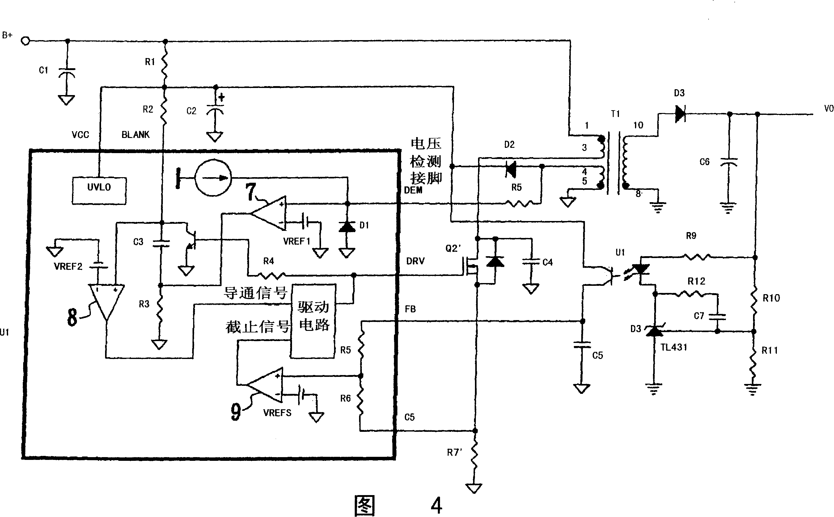
[0026]Fig. 4 is the quasi-resonance control circuit diagram of the power supply of the preferred embodiment of the present invention, as shown in the figure, the quasi-resonance control circuit is supplied with the voltage required for control by the power supply voltage VCC pin, and the quasi-resonance control circuit includes An undervoltage protection circuit UVLO (UNDERVOLRAGE LOCKOUT), to ensure that the starting resistor R1 is charged to the capacitor C2, and the power supply voltage VCC has sufficient voltage to start output, preventing abnormal circuit operation from damaging components. A voltage detection pin DEM is responsible for detecting the valley position of the voltage waveform a...


PUM


Abstract

The present invention provides a quasi-resonant control circuit of power supplies and the control method . The present invention utilizes a control circuit formed by simple electric components and the control method to control a power transistor to conduct when the power transistor and a transformer is at zero voltage level, so as to reduce the switching loss when the conduction of the power transistor is conducted.

Description

【Technical field】 [0001] The present invention relates to a quasi-resonance control circuit and a control method for a power supply, in particular to conduction between a power transistor and a transformer contact at a zero-voltage level, thereby reducing switching losses of the power transistor. 【Background technique】 [0002] Quasi-resonant flyback switching power supplies have been widely used in the market in order to reduce switching loss and electromagnetic interference noise generated during conduction. Figure 1 is a conventional flyback quasi-resonant control circuit diagram, called RCC (Ring Choke Converter) flyback circuit topology, please refer to Figure 1, when the DC power supply B+ power supply is turned on, a small current is first provided through a resistor R1 to slowly Charging turns on the power transistor Q1, and the primary side current starts to flow to the flyback transformer T1, power transistor Q1 and current detection resistor R10 to the negative po...

Claims


Application Information

Patent Timeline
Patent Type & Authority Applications(China)
IPC IPC(8): G05F1/12H02M7/44
Inventor 徐达经杨惠强
Owner NIKO SEMICON
Why Eureka
Try Eureka