
Rator unit, method for manufacturing the rator unit, motor and pump having the same

A technology of a rotor unit and a manufacturing method, applied in the fields of motors and pumps, can solve problems such as failure of electronic parts, poor electrical connection, warpage of a circuit substrate 3, etc., and achieve the effects of improving close contact, preventing warping, and narrowing gaps

Inactive Publication Date: 2008-04-02
NIDEC SHIBAURA CORP
View PDF1 Cites 20 Cited by
  • Summary
  • Abstract
  • Description
  • Claims
  • Application Information

AI Technical Summary

Benefits of technology

The technical effect described this patented technology relates to improving the reliability and performance of electronic devices such as motors or pumps used within industrial environments where they are subjected to various environmental factors like temperature changes (hot/cold) during use. By reducing exposures to moisture, dusts, dirt, and other contaminants, these technologies help maintain their functionality over time while ensuring consistently good quality products.

Problems solved by technology

This technical problem addressed in this patents relates to improving the quality control during production of integrated circuited rotors used within motors/pumps that use these devices. Specifically, current methods involve injecting resin into specific areas around certain conductive elements inside the device's housing before curing them together. These techniques can lead to insulation failure issues caused by thermal expansion mismatches from different materials being mixed up next time they work differently. Additionally, there could also cause damage to sensitive electronics located near those points where connections were previously established through solder joints.

Method used

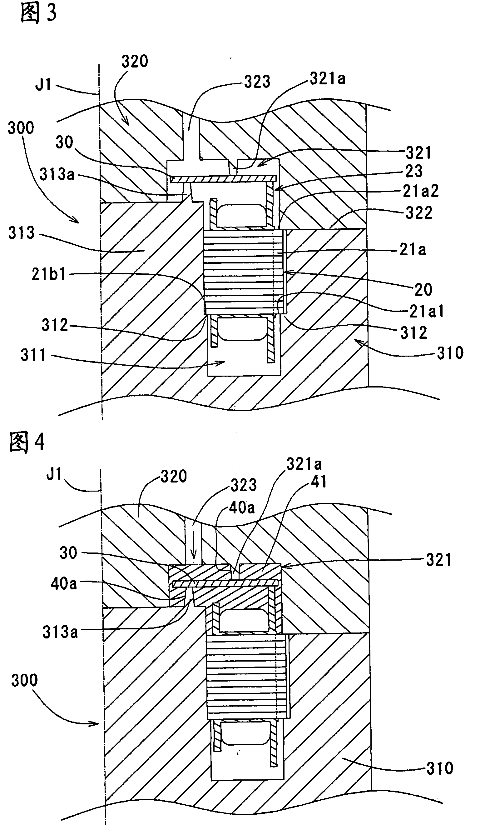
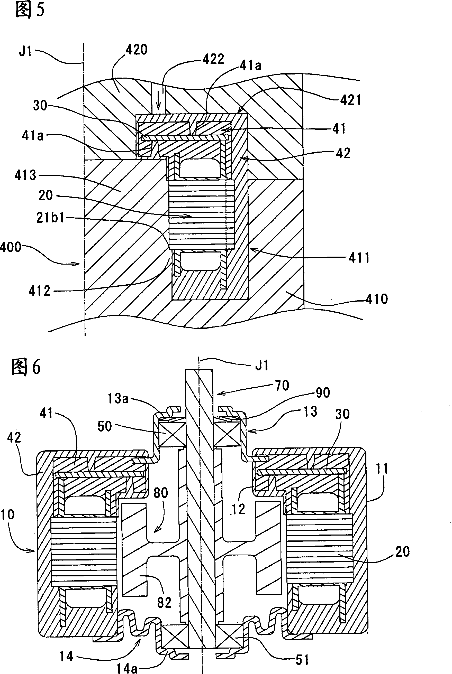

Image

  • Rator unit, method for manufacturing the rator unit, motor and pump having the same
  • Rator unit, method for manufacturing the rator unit, motor and pump having the same
  • Rator unit, method for manufacturing the rator unit, motor and pump having the same

Examples


Embodiment Construction

[0073] [Overall structure of the rotor unit]

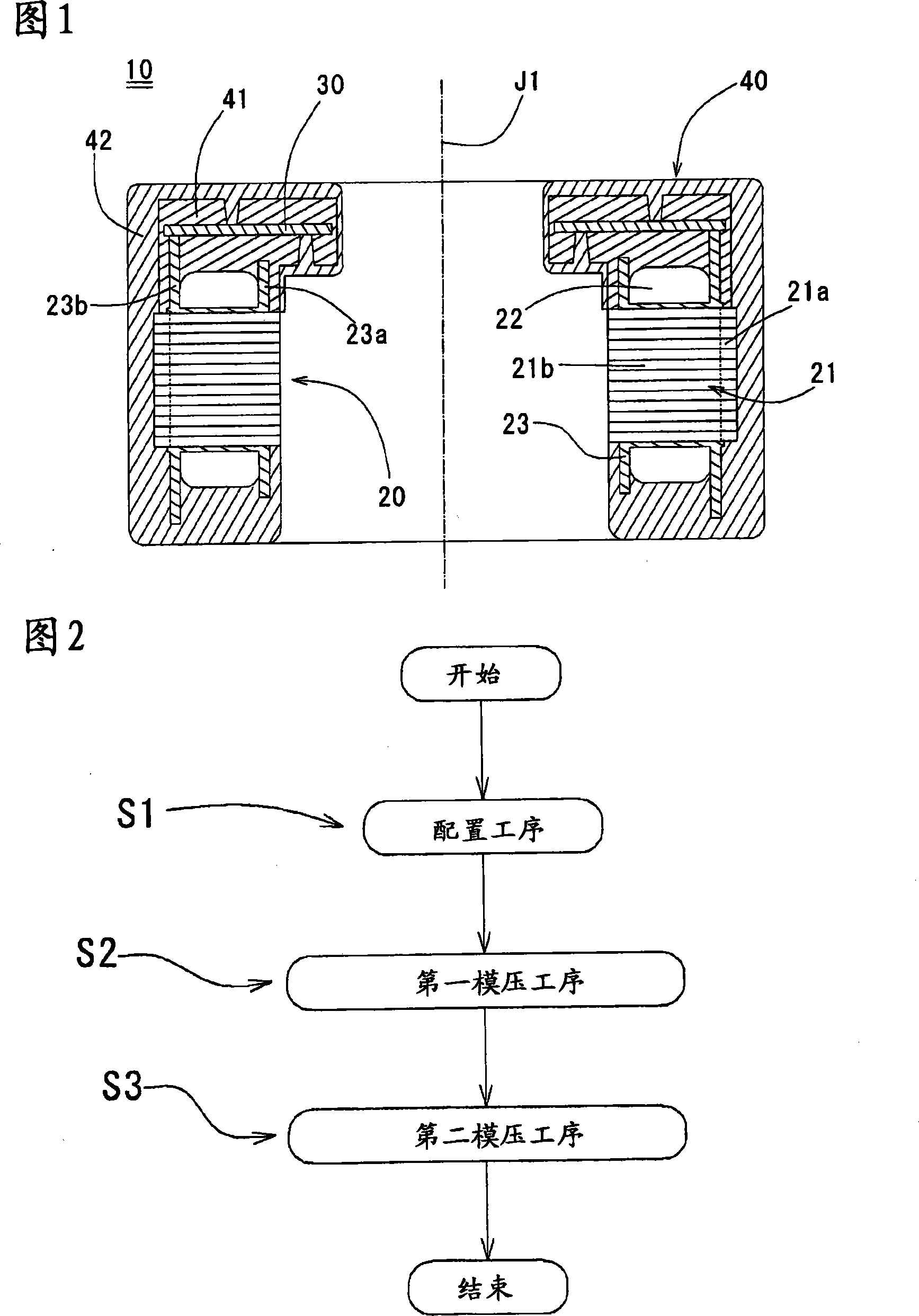
[0074] One mode of an embodiment of the overall structure of the rotor unit of the present invention will be described with reference to FIG. 1 . FIG. 1 is a schematic cross-sectional view cut along the axial direction showing one mode of an embodiment of a rotor unit. Here, the axial direction in FIG. 1 is the direction along the axis J1. In addition, the expressions of the upper side and the lower side in the following specification are expressions in the drawings, and do not specify the direction of gravity.

[0075] Referring to FIG. 1 , the rotor unit 10 has a rotor 20 , a circuit board 30 disposed on the axially lower side of the rotor 20 , and a molded portion 40 that molds the rotor 20 and the circuit board 30 .

[0076] The rotor 20 has a stator core 21 formed by laminating thin magnetic steel plates in the axial direction of a predetermined axis J1, a coil 22 formed by laminating electric wires in multiple layers and w...


PUM


Abstract

A rotor unit unable to generate bad appearance of the moulded part and bad conducting of the return circuit substrate, a method for manufacturing rotor unit and a motor and pump with the rotor unit are provided in the present invention. In the present invention, the moulded part (40) of the rotor unit (10) is composed of a first moulded part (41) covering peripheral of the return circuit substrate (30) and a second moulded part covering the peripheral of the first moulded part (41) and covering integral of the rotor (20). Under the low pressure state forming the first moulded part (41) can prevent the return circuit substrate (30) from warping and breaking when processing moulding. Then, by using the second moulded part (42), covering peripheral of the first moulded part (41), can fully prevent the return circuit substrate from external protruding, can prevent electricity from short circuit generated due to external water or water adhering on the return circuit substrate (30).

Description


Claims


Application Information

Patent Timeline
Owner NIDEC SHIBAURA CORP
Learn More