
Linear electric motor with movable armature core

An armature core and linear motor technology, applied in the field of armature core movable linear motors, can solve the problems of low motor performance-to-volume ratio, uneven distribution of excitation magnetic field along the axial direction, etc., to achieve improved performance-to-volume ratio and uniform distribution. Effect

Inactive Publication Date: 2008-04-02
TIANJIN DEXIN ELECTRIC MACHINERY
View PDF0 Cites 0 Cited by
  • Summary
  • Abstract
  • Description
  • Claims
  • Application Information

AI Technical Summary

Problems solved by technology

[0002] The traditional cylindrical hybrid linear motor has uneven distribution of the excitation field along the axial direction, and the performance-to-volume ratio of the motor is low

Method used


Image

  • Linear electric motor with movable armature core

Examples


Embodiment

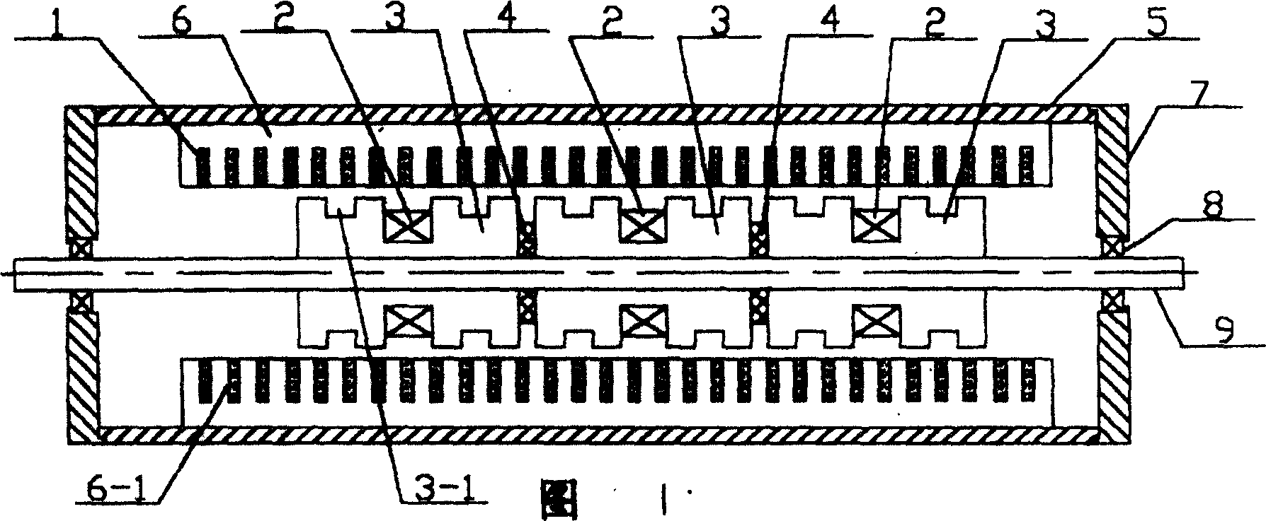
[0007] Embodiment: a linear motor with a movable armature core, two end covers 7 are respectively connected to both ends of the casing 5, the outer rings of the two bearings 8 are respectively fixed in the inner holes of the two end covers 7, the bearings 8 The inner ring is fixedly connected with the shaft 9, the armature core 3 is set on the shaft 9, the outer circular surface of the cylindrical non-armature core 6 is closely matched with the inner surface of the casing 5, the armature core 3 and the non-armature core An air gap 10 is formed between the 6. The armature core 3 and the non-armature core 6 face the air gap 10 on the surface of which there are annular cogging in sequence along the axial direction. The permanent magnet 1 is arranged on the cogging 6 of the non-armature core 6. -1 in.


PUM


Abstract

The invention relates to a linear motor with a movable armature core. Two end covers are separately connected with two ends of a shell; the outer rings of two bearings are respectively fixed inside the inner holes of the two end covers; the inner ring of the bearing is connected with an axle; the axle is sheathed with the armature core; the outer periphery of a cylindrical non-armature core closely matches with the inner face of the shell; an air gap is formed between the armature core and the non-armature core; Annular tooth spaces are arranged one by one along the axial direction on the surface of the armature core and the non-armature core facing the air gap; each tooth space on the non-armature core is provided with a permanent magnet. The invention has the advantages of evenly distribution of the exciting magnetic field along with the axial direction and the improved performance-volume ratio of the motor.

Description

technical field [0001] The invention relates to a movable linear motor with an armature iron core. Background technique [0002] In the traditional cylindrical hybrid linear motor, the excitation magnetic field is unevenly distributed along the axial direction, and the performance-to-volume ratio of the motor is low. Contents of the invention [0003] The object of the present invention is to overcome the above defects and provide a linear motor with movable armature core. [0004] The technical solution of the present invention is: a movable armature core linear motor, characterized in that: two end covers are respectively connected to the two ends of the casing, and the outer rings of the two bearings are respectively fixed in the inner holes of the two end covers Among them, the inner ring of the bearing is fixedly connected with the shaft, the armature core is set on the shaft, the outer circular surface of the cylindrical non-armature core is closely matched with the...

Claims


Application Information

Patent Timeline
Patent Type & Authority Applications(China)
IPC IPC(8): H02K41/02
Inventor 马长富
Owner TIANJIN DEXIN ELECTRIC MACHINERY
Learn More