Ethernet switching system and equipment

A switching device and Ethernet technology, applied in the field of network communication, can solve problems such as limited number of ports, large equipment resource consumption, abnormal operation of equipment, etc., and achieve the effect of improving reliability

Inactive Publication Date: 2008-04-02
HUAWEI TECH CO LTD
View PDF0 Cites 38 Cited by
  • Summary
  • Abstract
  • Description
  • Claims
  • Application Information

AI Technical Summary

Problems solved by technology

[0006] STP consumes a lot of device resources (CPU, memory), and a general device supports a limited number of STP-enabled ports, which cannot support large-scale net

Method used


Image

  • Ethernet switching system and equipment
  • Ethernet switching system and equipment
  • Ethernet switching system and equipment

Examples


Embodiment Construction

[0033] Throughout the specification, the preferred embodiment and examples shown should be considered as exemplifications of the invention and not as limitations.

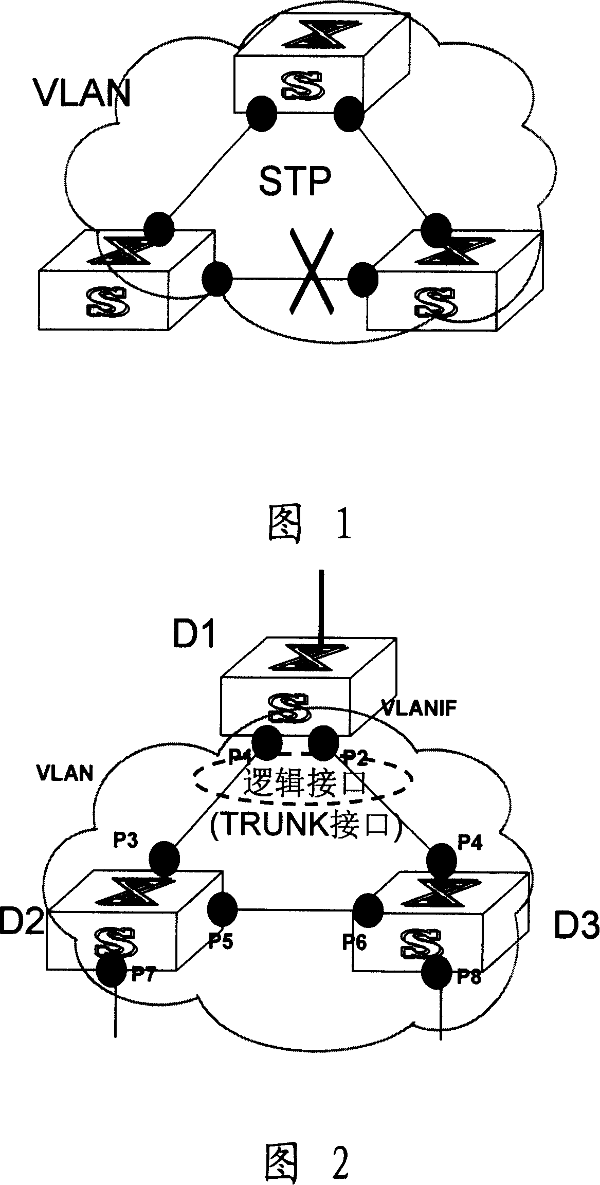
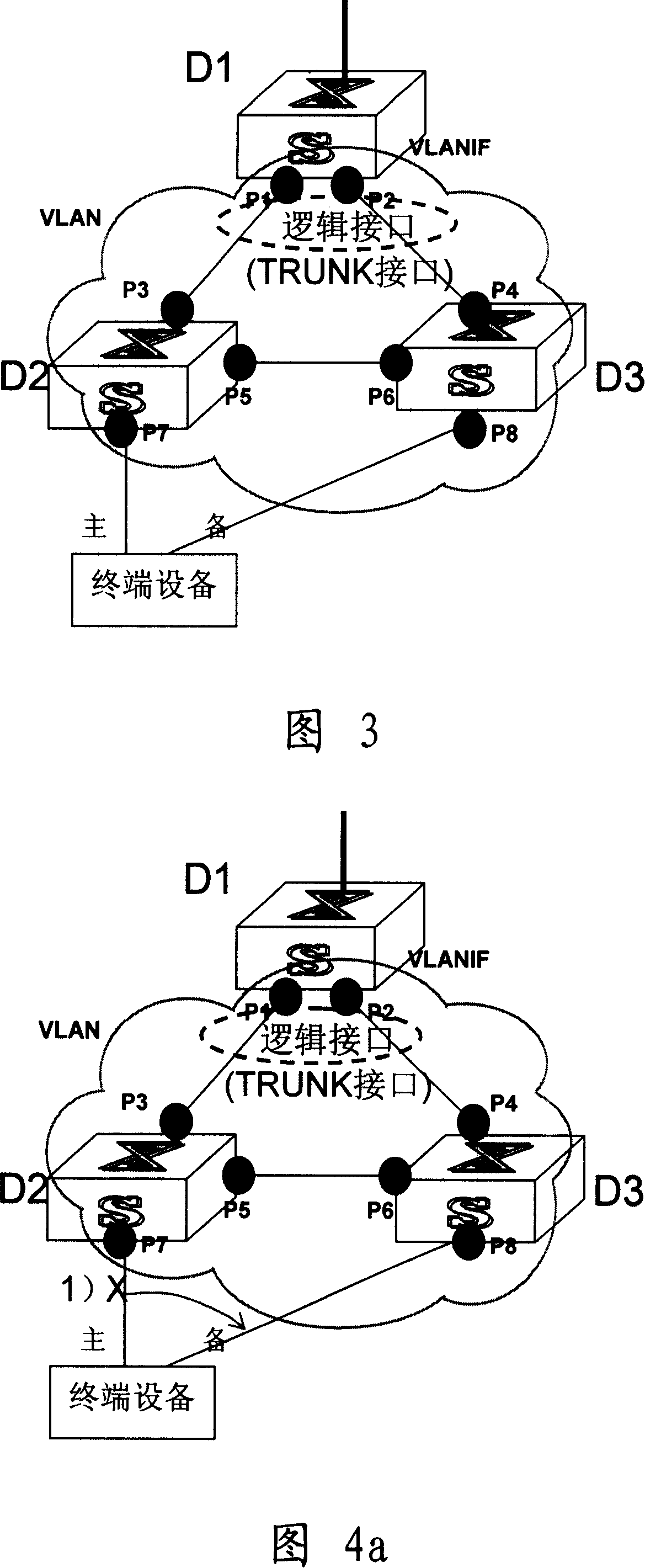
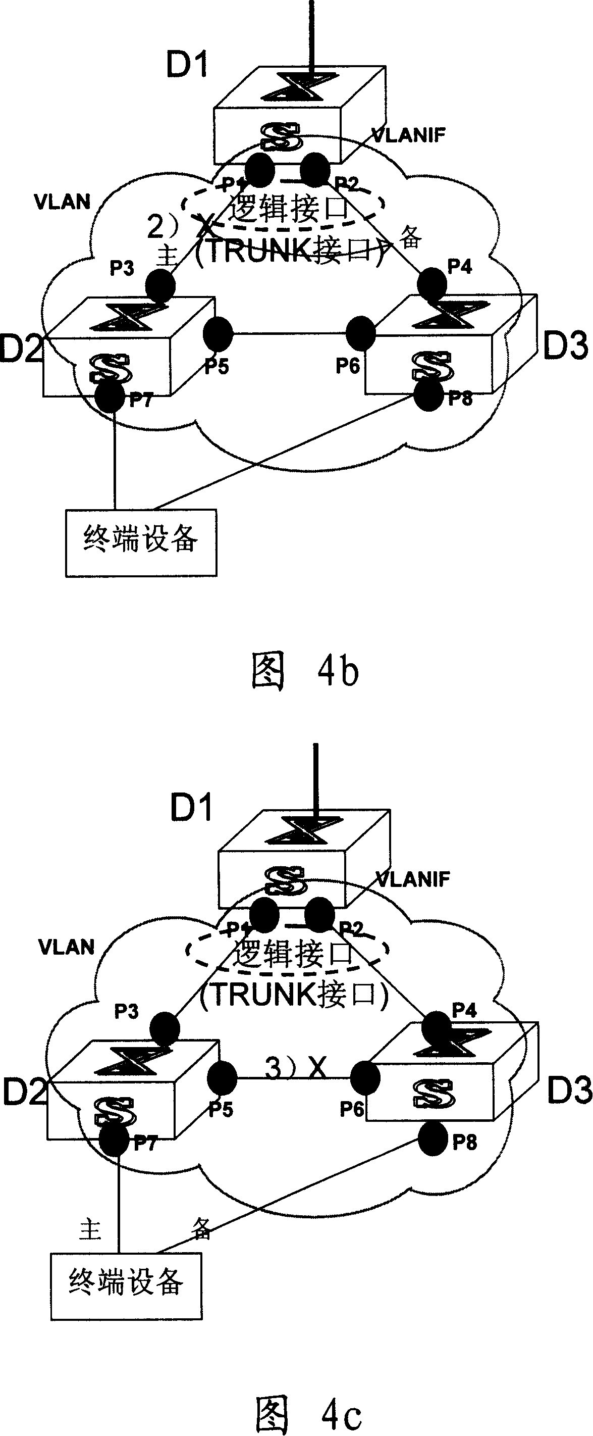
[0034] As shown in FIG. 2, D1, D2, and D3 are devices with an Ethernet switching function, such as an Ethernet switch or a router supporting a VLAN function. The black circles P1 to P8 in Figure 2 represent physical ports. Physical ports P1 and P8 are added to the same VLAN. Among them, physical ports P1 and P2 belong to device D1, physical ports P3, P5, and P7 belong to device D2, and physical ports P4 , P6, and P8 belong to the device D3. Different from other physical ports, P7 and P8 are generally connected to terminal devices, such as PCs, servers, and UMG (Universal Media Gateway) in softswitches.

[0035] The physical ports P1 and P2 of device D1 are bundled to form a logical interface. This logical interface is a port backup group. The port backup group includes a main port and a backup port. Under normal c...


PUM


Abstract

The invention discloses an Ethernet exchanging system and device. A copy group composed of two physical terminals of the Ethernet exchanging device is added into a logic interface and the said logic interface belongs to a certain virtual local area network VLAN, the said physical terminals in the adjacent VLAN are connected to form a network loop. The two physical terminals of the logic interface are respectively divided into main terminal and spare terminal, the main terminal is used for sending and receiving the message and the main terminal and the spare terminal of the same logic interface do not transmit the same message. The invention also provides an Ethernet exchanging device. The said invention can prevent the broadcast loop in VLAN, implement quickly protect switch and reverse switch in VLAN, at the same time solve the problem that the protect switch and reverse switch of Ethernet exchanger is unreliable in NGN load-carrying net.

Description

technical field [0001] The invention relates to the technical field of network communication, in particular to an Ethernet switching system and equipment. Background technique [0002] Virtual Local Area Network (VLAN for short) is a technology that realizes a virtual workgroup by logically rather than physically dividing devices in a local area network into network segments. VLAN technology allows network managers to logically divide a physical LAN into different broadcast domains (or virtual LANs, or VLANs). Therefore, each computer in the same VLAN does not need to be placed in the same physical space, that is, these computers do not necessarily belong to the same physical LAN segment. [0003] Hosts in a VLAN can communicate directly, but not between VLANs. In this way, broadcast packets are limited to one VLAN. In addition to dividing broadcast domains, VLAN can also meet more complex network applications, help control network traffic, reduce equipment investment, sim...

Claims


Application Information

Patent Timeline
IPC IPC(8): H04L12/46H04B1/74H04L1/22H04L12/04
Inventor 刘珺吕俊洋杨平安
Owner HUAWEI TECH CO LTD
Why Eureka
Try Eureka