Power flow configuration for dual clutch transmission mechanism

A technology of clutch and automobile transmission, applied in the direction of vehicle gearbox, transmission, mechanical equipment, etc., can solve the problems of limited transmission, expensive, large synchronizer, etc., and achieve the effect of reducing pressure, complexity and cost

Inactive Publication Date: 2011-11-09
BORGWARNER INC
View PDF1 Cites 0 Cited by
  • Summary
  • Abstract
  • Description
  • Claims
  • Application Information

AI Technical Summary

Problems solved by technology

For example, synchronizers for first gear are typically larger and more expensive than synchronizers for other gears, and can create additional durability and service issues for different more complex structures, such as multi-cone synchronizers
[0014] In addition, the pinion and gear arrangement limits the minimum diameter (perpendicular to the axis of the layshaft) and minimum length (parallel to the axis of the layshaft) of the variator

Method used


Image

  • Power flow configuration for dual clutch transmission mechanism
  • Power flow configuration for dual clutch transmission mechanism
  • Power flow configuration for dual clutch transmission mechanism

Examples


example

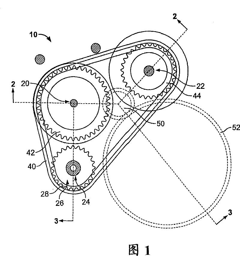
[0134] An illustration of the advantages of some aspects of the dual clutch transmission disclosed herein can be shown by selecting sprocket, pinion and gear configurations, such as the following configurations for the dual clutch transmission mechanism 500, which has five forward speeds and one reverse Gear speeds are stated based on the number of teeth of sprockets 528, 542, 544, gears 552, 554, and 556, or pinions 570, 572, 574, 576, 578, and 582:

[0135] Gears / Sprockets

Number of teeth

Input sprocket(528)

24

Odd input sprockets (542)

42

Even input sprocket(544)

56

First gear(570)

17

Second gear(572)

29

Third gear(574)

31

Fourth gear(576)

39

Fifth gear(578)

38

Reverse gear(582)

19

First gear driven(552)

39

2nd gear / 3rd gear / reverse gear driven(554)

27

Fourth gear / fifth gear driven(...


PUM


Abstract

A transmission mechanism with a pair of selectively engageable clutch systems is disclosed that has an upstream gear ratio and a downstream gear ratio that combine to provide an effective gear ratio. A different clutch drive member is associated with an input side of each of the pair of clutch systems. The clutch drive members are driven for rotation by an engine input member. The upstream gear ratio is determined by the gear ratio between the engine input member and one of the clutch drive members. Output sides of each of the clutch systems drive an associated one of a pair of non-coaxial layshafts. Pinions are located on and selectively driven by the layshafts. A countershaft is spaced from both of the layshafts, and has a plurality of gears. Each of the gears is driven for rotation by one of the pinions of the layshafts. The downstream gear ratio is determined by the gear ratio between the selected pinion and the intermeshed gear.

Description

technical field [0001] The present disclosure relates to a dual clutch transmission, and more particularly to a dual clutch transmission with an improved mechanism and a method of using the power flow of a dual clutch transmission. Background technique [0002] A typical motor vehicle transmission utilizes a common input shaft from the engine to a series of gears (which may also be referred to as "pinions ( pinion)") to provide the driving force, the series of gears are aligned and mesh with corresponding gears on a parallel output shaft (which may also be referred to as a "countershaft"). Specific combinations of corresponding pinion gears on the layshaft and gears on the countershaft can be selected to provide different gear ratios for transmitting torque in different, typically overlapping speed ranges. [0003] Rather, the corresponding pinion and gear combination provides the gear ratio for transferring torque and rotation from the engine to downstream components of th...

Claims


Application Information

Patent Timeline
Patent Type & Authority Patents(China)
IPC IPC(8): F16H3/00
CPCF16H2003/0822F16H3/006F16H2200/0052F16H2200/0047F16H3/08F16H3/10F16H3/093F16H61/688Y10T74/19228Y10T74/19233Y10T74/19284F16H3/00
Inventor T·E·布拉福德
Owner BORGWARNER INC
Why Eureka
Try Eureka