
System to reduce crankshaft speed variations

a technology of crankshaft speed variation and crankshaft, which is applied in the direction of engine controllers, machines/engines, electric control, etc., can solve the problems of inability to reduce noise and vibration, damage to the clutch, etc., and achieve the effect of increasing increasing the current, and reducing the rotor torque load

Inactive Publication Date: 2007-11-15
GM GLOBAL TECH OPERATIONS LLC
View PDF13 Cites 23 Cited by
  • Summary
  • Abstract
  • Description
  • Claims
  • Application Information

AI Technical Summary

Benefits of technology

[0006] In yet other features, the braking device is an electric machine having a rotor. The control module selectively synchronizes a rotor rotational torque load with the crankshaft rotational speed. The control module increases a rotor torque load by increasing the current through the rotor when the crankshaft rotational speed is increasing. The control module decreases the rotor torque load by decreasing the current in the rotor when the crankshaft rotational speed is decreasing.

Problems solved by technology

Periodically locking and unlocking the converter clutch may damage to the clutch.
Periodically locking and unlocking may also cause unacceptable levels of noise and vibration.

Method used


Image

  • System to reduce crankshaft speed variations
  • System to reduce crankshaft speed variations
  • System to reduce crankshaft speed variations

Examples


Embodiment Construction

[0015] The following description of the preferred embodiment(s) is merely exemplary in nature and is in no way intended to limit the invention, its application, or uses. For purposes of clarity, the same reference numbers will be used in the drawings to identify similar elements. As used herein, the term module refers to an application specific integrated circuit (ASIC), an electronic circuit, a processor (shared, dedicated, or group) and memory that execute one or more software or firmware programs, a combinational logic circuit, and / or other suitable components that provide the described functionality.

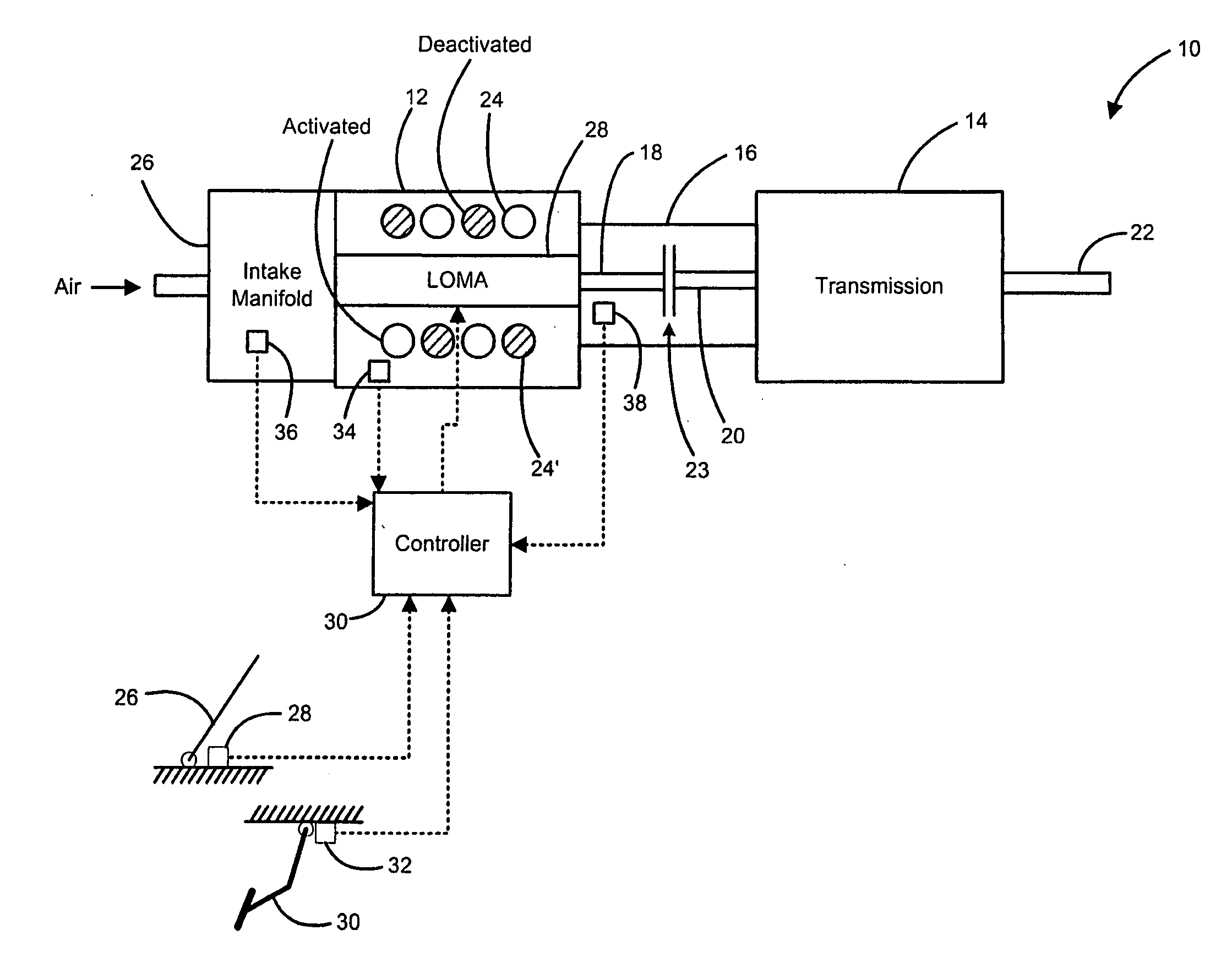
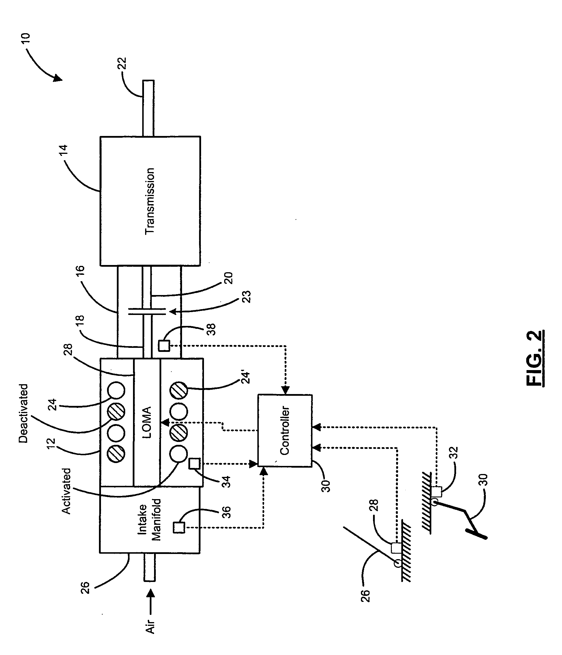
[0016] Referring now to FIG. 2, a vehicle 10 includes an engine 12 that drives a transmission 14. The transmission 14 is an automatic transmission and is driven by the engine 12 through a corresponding torque converter 16. More specifically, the engine 12 generates drive torque to drive a crankshaft 18. The crankshaft 18 is selectively coupled to an input shaft 20 of the transmissio...


PUM


Abstract

A system to reduce rotational speed variations of a crankshaft includes a controller, a braking device, and a control module. The controller deactivates at least one cylinder in an internal combustion engine. The braking device applies a braking torque to the crankshaft when at least one cylinder is deactivated. The control module determines whether the controller has deactivated at least one cylinder and selectively synchronizes the braking torque with a crankshaft rotational speed.

Description

FIELD OF THE INVENTION [0001] The present invention relates to internal combustion engines, and more particularly to reducing speed variations of a crankshaft associated with an internal combustion engine. BACKGROUND OF THE INVENTION [0002] In a vehicle with an automatic transmission, a crankshaft is typically connected to the transmission using a torque converter. The torque converter includes a pump and a turbine. The pump is connected to the crankshaft and rotates at the same speed as the crankshaft. The turbine is connected to the transmission and rotates at the same speed as the transmission. The torque converter allows the crankshaft to spin somewhat independently from the transmission. If the engine is rotating slowly, the amount of torque transferred by the torque converter is low, which allows the vehicle to come to a stop while the engine continues to rotate. At steady vehicle speeds, the transmission and crankshaft operate at nearly the same speed, which transfers torque ...

Claims


Application Information

Patent Timeline
Patent Type & Authority Applications(United States)
IPC IPC(8): F02B75/06
CPCB60W10/06B60W10/08B60W30/20B60W2510/0652F02D2250/24F02D41/0087F02D41/083F02D41/1498F02D17/02
Inventor ALBERTSON, WILLIAM C.MC DONALD, MIKE M.
Owner GM GLOBAL TECH OPERATIONS LLC
Learn More