
Method and apparatus for liquefying a natural gas stream

A technology of natural gas and gas flow, applied in lighting and heating equipment, liquefaction, refrigeration and liquefaction, etc., can solve the problems of insufficient and complicated recovery of compounds, and achieve the effect of increasing recovery, maintaining the same refrigeration power and increasing production.

Inactive Publication Date: 2008-04-02
SHELL INT RES MAATSCHAPPIJ BV
View PDF2 Cites 3 Cited by
  • Summary
  • Abstract
  • Description
  • Claims
  • Application Information

AI Technical Summary

Problems solved by technology

[0005] The problem with the method according to DE 102 26 597 is that it is unnecessarily complicated
Another problem with the above method is that the recovery of compounds heavier than methane, especially propane and butane, is insufficient

Method used


Image

  • Method and apparatus for liquefying a natural gas stream

Examples


Embodiment Construction

[0046] For purposes of illustration, a single reference number will be assigned to a pipeline and the streams carried in that pipeline. Like reference numbers refer to like components.

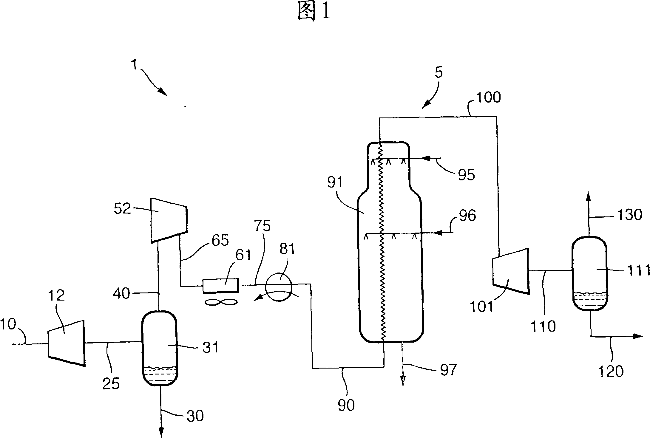
[0047] Figure 1 schematically shows a baseload liquefied natural gas (LNG) export process and an apparatus (indicated generally with reference numeral 1) for carrying out the export process. After being expanded in the expander 12, the feed stream 10 containing natural gas is supplied to the gas / liquid separator 31 at a specific inlet pressure and inlet temperature. Typically, the pressure of stream 10 will be between 30 bar and 80 bar (preferably >60 bar and <70 bar), and the temperature will be close to ambient, usually between 5°C and 50°C.

[0048] If desired, feed stream 10 may be pretreated prior to its introduction into expander 12 . For example, feed stream 10 may be pre-cooled by coolant in one heat exchanger (not shown), or in a series of heat exchangers, for example comprising two...


PUM


Abstract

The present invention relates to a method of liquefying a natural gas stream, wherein the natural gas stream (10) is provided at a pressure of 30-80 bar, expanded to a pressure < 35 bar, supplied to a gas / liquid separator (31) and therein into a vaporous stream (40) and a liquid stream (30). The pressure of the vaporous stream is increased to a pressure of at least 70 bar and the pressurized vaporous stream (90) is liquefied to obtain a liquefied natural gas stream.

Description

technical field [0001] The present invention relates to a method of liquefying a natural gas stream. Background technique [0002] Several methods of liquefying natural gas streams to obtain liquefied natural gas (LNG) are known. Liquefied natural gas streams are desired for several reasons. As an example, natural gas can be stored and transported over long distances more easily in liquid than in gaseous form because it occupies a smaller volume and does not need to be stored at high pressure. [0003] Examples of known processes for liquefying gases are disclosed eg in US 6 272 882 and DE 10 226 597 A1. [0004] According to Figure 1 of DE 102 26 597 A1, a natural gas stream at a pressure of 70-100 bar is expanded (expander X) to a pressure range of 40-70 bar, cooled (heat exchanger E1) and fed to heavy hydrocarbons (HHC ) tower (T1). The C-rich product removed from the top of the HHC column 2 The fraction is further cooled (E2) and fed to another column (D). The top ...

Claims


Application Information

Patent Timeline
IPC IPC(8): F25J1/02
CPCF25J1/0035F25J2220/64F25J2220/62F25J1/0022F25J1/0214F25J1/0216F25J1/0055F25J2205/02F25J1/0042F25J2230/60F25J1/0238F25J1/02
Inventor C·布伊斯W·达姆E·C·J·N·德容
Owner SHELL INT RES MAATSCHAPPIJ BV
Features
  • Generate Ideas
  • Intellectual Property
  • Life Sciences
  • Materials
  • Tech Scout
  • Unparalleled Data Quality
  • Higher Quality Content
  • 60% Fewer Hallucinations
Learn More