Novel thermal recovery well head device

A wellhead device, thermal recovery technology, applied in the fields of fluid production, earth-moving drilling, wellbore/well components, etc.

Inactive Publication Date: 2008-04-09
LIAOHE GASOLINEEUM EXPLORATION BUREAU
View PDF0 Cites 3 Cited by
  • Summary
  • Abstract
  • Description
  • Claims
  • Application Information

AI Technical Summary

Problems solved by technology

[0003] The purpose of the present invention is to provide a new type of thermal recovery wellhead device, which solves the problem in the prior art that the conventional thermal recovery wellhead needs to lift all the sucker rods before performing steam injection when it is unblocked or unsealed. The problem

Method used


Image

  • Novel thermal recovery well head device

Examples


Embodiment Construction

[0009] The invention is given by the following examples.

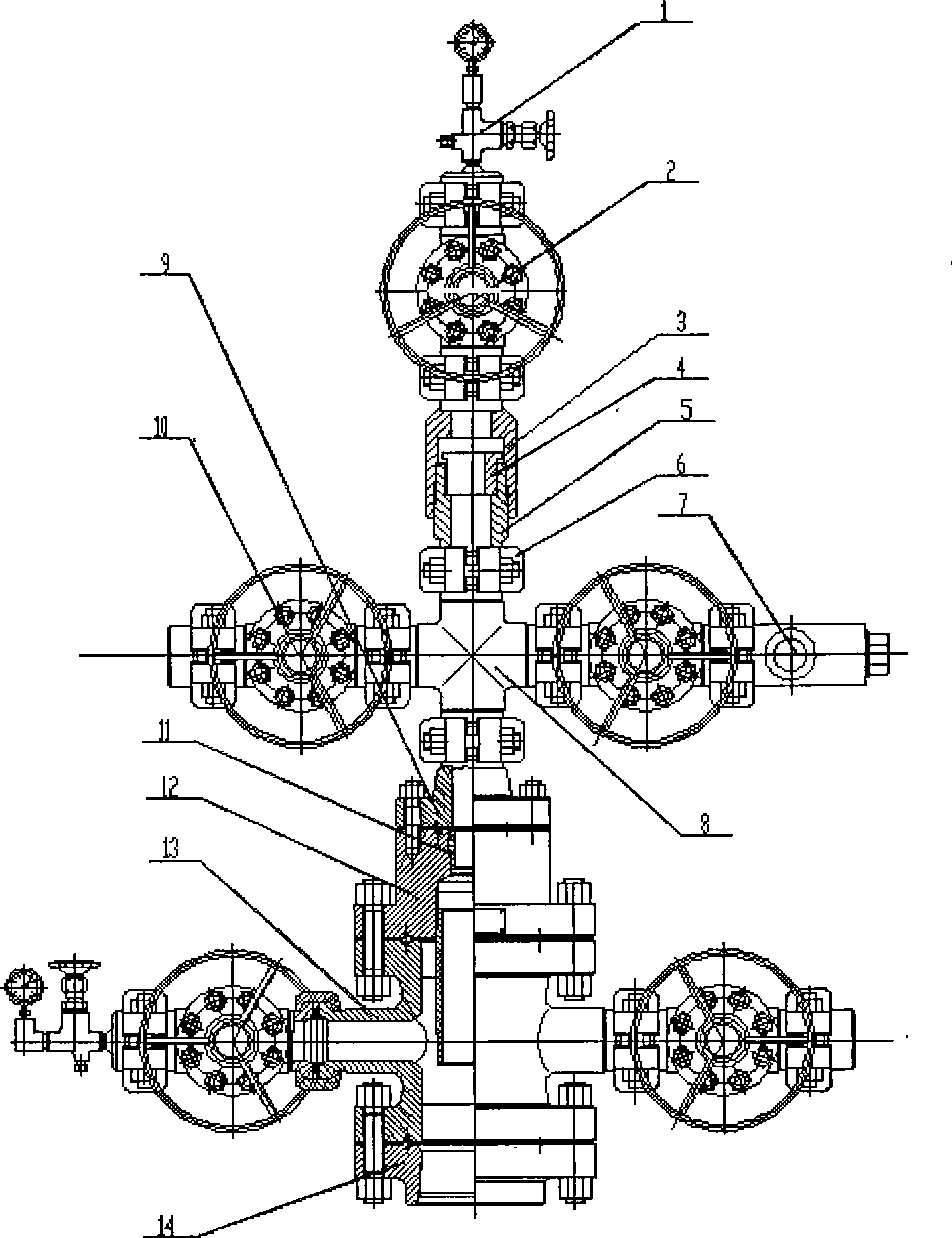
[0010] In the accompanying drawings, a new type of thermal recovery wellhead device consists of a needle-shaped air release valve 1, a closed gate valve 2, an upper threaded clamp reducing diameter 3, a card seat 4, a lower threaded clamp reducing diameter 5, a clamp 6, a throttling 7, small cross 8, flange clamp reducer 9, wing valve 10, protective wire 11, upper flange 12, large cross 13, casing flange 14; needle-shaped air release valve 1 and closed gate valve 2. Lower threaded clamp reducer 5 and small cross 8, small cross 8 and flange clamp reducer 9, restrictor 7 and wing valve 10 are all connected by clamp 6, and clamp 4 sits on the lower thread clamp On the upper step of hoop reducer 5, the upper threaded clamp reducer 3 is threadedly connected with the lower threaded clamp reducer 5, and the protective wire 11 is tightened to protect the thread in the upper flange 12. Firstly, the casing flange 14 and the larg...


PUM


Abstract

The invention relates to a novel heat-extraction well-mouth device used for an oil field extraction work, which consists of a needle air-releasing valve, a seal gate valve, an upper thread clamp-loop variable diameter, a clamp seat, a lower thread clamp-loop variable diameter, a clamp-loop, a restrictor, a small four-way device, a flange clamp-loop variable diameter, a wing valve, a screw protector, an upper flange, a big four-way device and a bushing flange. The needle air-releasing valve and the seal gate valve, the lower thread clamp-loop variable diameter and the small four-way device, the small four-way device and the flange clamp-loop variable diameter, and the restrictor and the wing valve are respectively connected by the clamp loops. The clamp seat is seated on an upper step of the lower thread clamp-loop variable diameter, and the upper thread clamp-loop variable diameter is screwed with the lower thread clamp-loop variable diameter, and the screw protector is tightened in the upper flange. And the bushing flange is firstly connected with the big four-way device through the bolt, then a steel ring is put into and the upper flange is connected with the big four-way device through the bolt. The invention solves the problems of the prior art that a heavy load work cannot be done when a clamp-releasing or seal-releasing is done for a common heat-extraction well mouth; when in an air-injection, an oil pumping rob must be fully elevated and the air-injection work can be carried out. The invention can be widely applied to the oil field extraction work.

Description

Technical field: [0001] The invention relates to a novel thermal recovery wellhead device for oil recovery operations in oil fields. Background technique: [0002] At present, oil production in oilfields is general oil recovery operation and heavy oil thermal recovery operation. Steam flooding and steam injection thermal oil recovery are mainly used in heavy oil recovery. In the process of using ordinary thermal recovery wellhead device, the problem existing in this device is that the wellhead is not stuck or unblocked. During operation, because the tubing hanging flange has a narrow diameter and a small cross-section, it cannot carry a large load; when the wellhead steam injection operation is performed, all the sucker rods must be lifted before the steam injection operation can be performed. Retrieved by the Patent Retrieval Center of the State Intellectual Property Office on October 9, 2007, it has novelty and inventiveness (G072060) Invention content: [0003] The pur...

Claims


Application Information

Patent Timeline
Patent Type & Authority Applications(China)
IPC IPC(8): E21B33/03E21B43/24
Inventor 刘福东潘耀庆李志杨杨杜晶春王永利贾振宇魏永捷
Owner LIAOHE GASOLINEEUM EXPLORATION BUREAU
Why Eureka
Try Eureka