Turbine rotor and steam turbine

A turbine rotor and steam turbine technology, applied in the field of steam turbines, can solve problems such as large thermal stress

Active Publication Date: 2008-04-09
KK TOSHIBA
View PDF3 Cites 8 Cited by
  • Summary
  • Abstract
  • Description
  • Claims
  • Application Information

AI Technical Summary

Problems solved by technology

[0007] However, in the above-mentioned conventional method of forming a turbine rotor by combining a Ni-based alloy and 12Cr steel, since there is a large difference between the linear expansion coefficient of the Ni-based alloy and that of the 12Cr steel, there are problems as follows: Generates large thermal stress at the joint

Method used


Image

  • Turbine rotor and steam turbine
  • Turbine rotor and steam turbine
  • Turbine rotor and steam turbine

Examples


no. 1 Embodiment approach

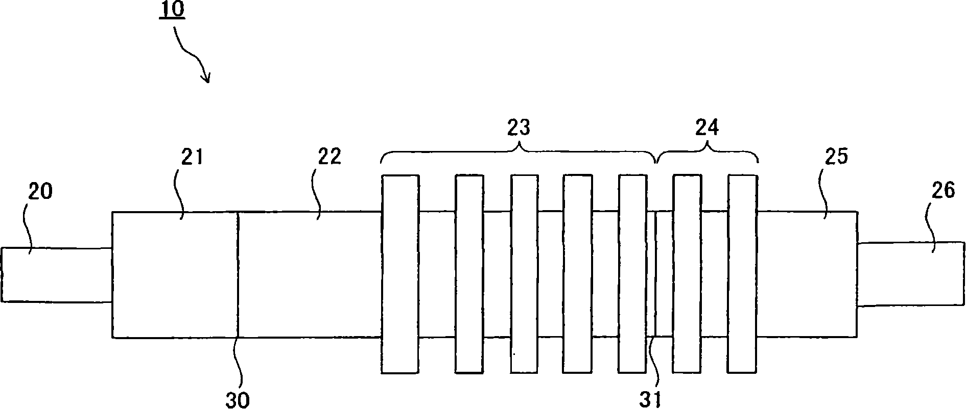
[0032] figure 1 It is a plan view schematically showing the configuration of the turbine rotor 10 according to the first embodiment of the present invention.

[0033] Such as figure 1 As shown, the turbine rotor 10 includes: a front shaft 20, a front low temperature sealing part 21, a front high temperature sealing part 22, a front high temperature moving blade part 23, a rear low temperature moving blade part 24, a rear low temperature sealing part 25, and rear axle 26 .

[0034] The front shaft 20 and the front cryogenic seal 21 are integrally formed. In addition, the front high-temperature sealing part 22 and the front high-temperature rotor blade part 23 in which the rotor blades are fitted are integrally formed. Furthermore, the rear shaft 26 , the rear low-temperature seal portion 25 , and the rear low-temperature rotor blade portion 24 in which the rotor blades are embedded are also integrally formed. In addition, the front low-temperature sealing part 21 is connect...

no. 2 Embodiment approach

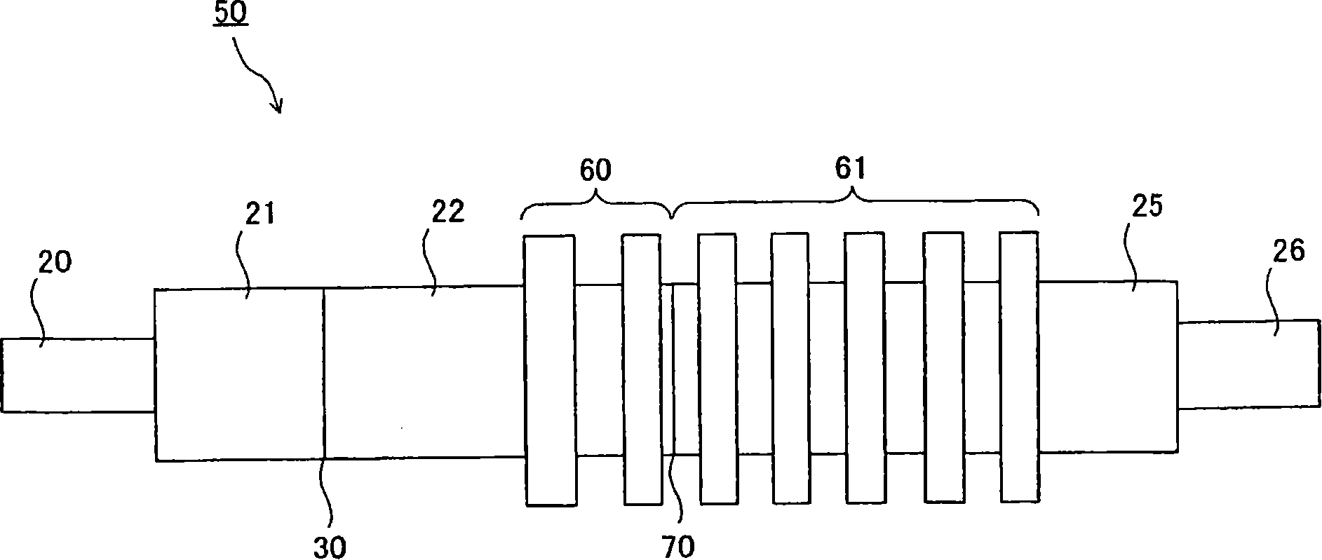
[0070] image 3 It is a plan view schematically showing the configuration of a turbine rotor 50 according to a second embodiment of the present invention. In addition, the same code|symbol is attached|subjected to the same component as the structure of the turbine rotor 10 of 1st Embodiment, and repeated description is abbreviate|omitted or simplified here.

[0071] Here, the configuration of the turbine rotor 50 of the second embodiment is the same as that of the first embodiment except that the configurations of the front high-temperature rotor blade portion 23 and the rear low-temperature rotor blade portion 24 of the turbine rotor 10 of the first embodiment are changed to provide a cooling mechanism. The configuration of the turbine rotor 10 of the first embodiment is the same. Such as image 3 As shown, the turbine rotor 50 includes: a front shaft 20, a front low temperature sealing part 21, a front high temperature sealing part 22, a front high temperature moving blade...

Embodiment 1 and comparative example 1

[0084]Here, the Ni-based alloy and CrMoV steel used in the turbine rotor of the present invention are used, and the Ni-based alloy and CrMoV steel are deposited to form a turbine rotor, which is assumed to be Test Sample 1 (Example 1). The Ni-based alloy and 12Cr steel used in the dissimilar welded turbine rotor were deposited on the Ni-based alloy and 12Cr steel to form the turbine rotor, which was assumed to be the test sample 2 (comparative example 1), and calculated in the respective Thermal stress at the junction.


PUM

PropertyMeasurementUnit
diameteraaaaaaaaaa
lengthaaaaaaaaaa
thermal stressaaaaaaaaaa

Abstract

A turbine rotor 10 is disposed in a steam turbine, into which high-temperature steam of 650°C or more is introduced, and separately configured of the portion made of the Ni-base alloy and the portion made of the CrMoV steel depending on a steam temperature and a metal temperature, and the individual portions having a small difference in coefficient of linear expansion are welded mutually.

Description

technical field [0001] The present invention relates to a turbine rotor formed by welding components of the divided turbine rotor, in particular to a turbine rotor in which each component is formed of a preferred heat-resistant alloy or heat-resistant steel, and a steam turbine having the turbine rotor. Background technique [0002] Regarding thermal power generation equipment including steam turbines, since the oil crisis, energy conservation has been vigorously promoted, and in recent years, from the perspective of protecting the global environment, CO 2 The emission-suppressed technology is compelling. As a part of this, the demand for higher equipment efficiency has been increased. [0003] In order to improve the power generation efficiency of a steam turbine, it is very effective to increase the steam temperature. In recent steam turbine thermal power generation equipment, the steam temperature has risen to over 600°C. In the future, the steam temperature of the stea...

Claims


Application Information

Patent Timeline
Patent Type & Authority Applications(China)
IPC IPC(8): F01D5/02
CPCF01D5/063F05D2220/31C22C38/02F05B2230/606F05B2220/301C22C38/04C22C38/22C22C19/055C22C38/24F05D2230/642Y10T29/4932
Inventor 福田雅文久保贵博
Owner KK TOSHIBA
Why Eureka
Try Eureka