Piezoelectrically excitable oscillation device

An oscillating device, a technology to stimulate oscillation, applied in the direction of measuring devices, lubrication indicating devices, engine lubrication, etc., can solve problems such as measurement of oscillating systems that are no longer possible, and achieve optimized transfer points, good oscillating transfers, and small diaphragm contact areas Effect

Inactive Publication Date: 2008-04-09
VEGA GRIESHABER GMBH & CO
View PDF3 Cites 5 Cited by
  • Summary
  • Abstract
  • Description
  • Claims
  • Application Information

AI Technical Summary

Problems solved by technology

They lead, in unfavorable cases, to no longer or almost no longer being able to measure the mechanical and electrical amplitudes of oscillating systems

Method used


Image

  • Piezoelectrically excitable oscillation device
  • Piezoelectrically excitable oscillation device

Examples


Embodiment Construction

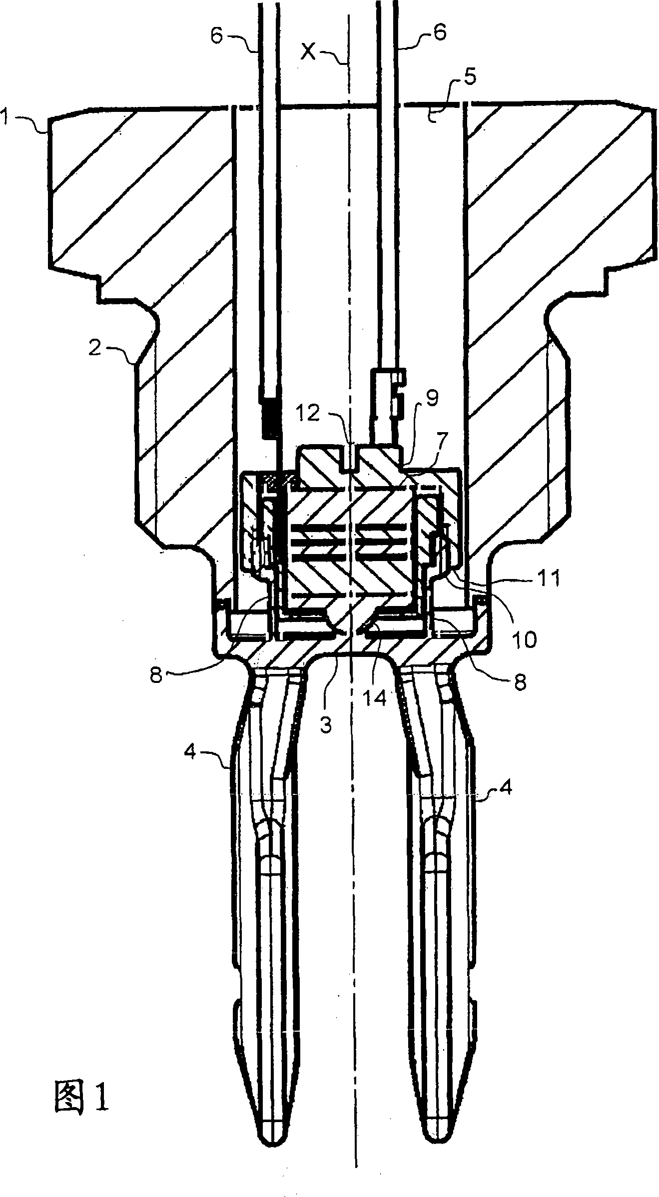
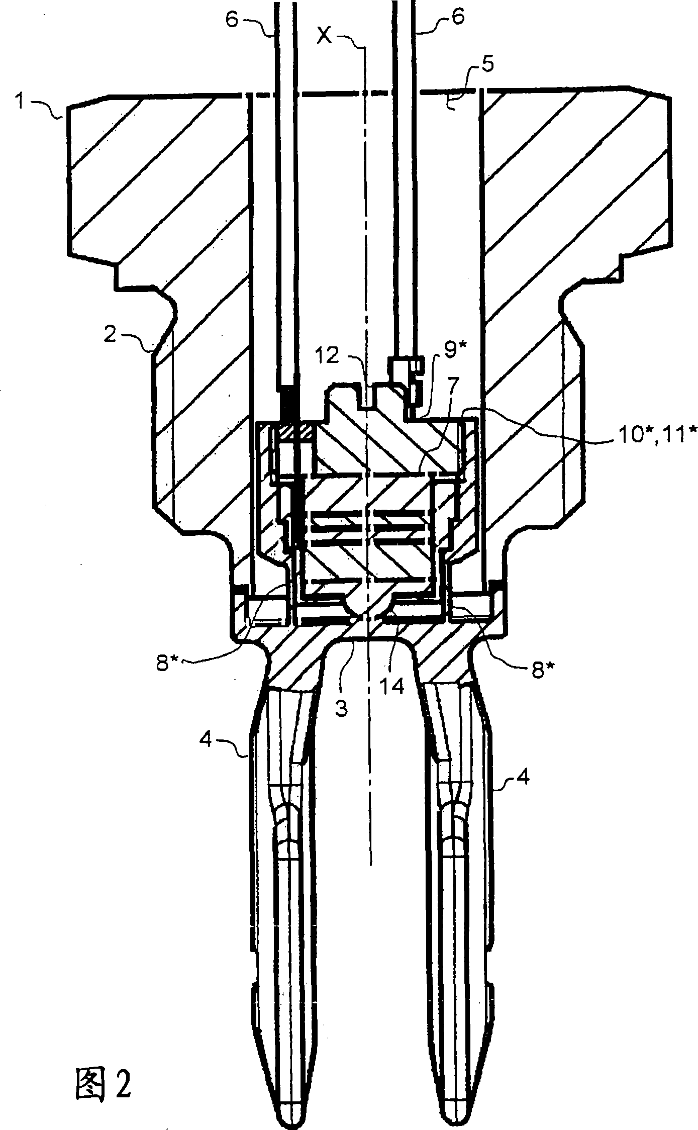
[0032] As shown in FIG. 1 , an oscillating device, which can be used in particular as a filling level or boundary state measuring device, consists of many parts. Only those components that are relevant to the understanding of the preferred embodiment are described in detail below. Accordingly, in particular other components and components described only in the periphery of the constituent parts of the preferred embodiment may be replaced by functionally identical or equivalent components in known manner.

[0033] Such an oscillating device usually has a housing 1 which has, in its peripheral region, a housing thread 2 for fastening the oscillating device in a threaded bore of a container. An oscillating diaphragm 3 is fastened to the end face of the housing 1 and in the mounted state protruding into such a container. The diaphragm 3 is usually fastened, in particular welded, to the end face of the housing 1 by means of a rear edge, ie formed by a flange in the direction of the ...


PUM


Abstract

The invention relates to an oscillatory device with peizoelectric incentive, especially the oscillatory device with filling level or boundary state. Formerly, the oscillatory device with piezoelectric incentive includes one membrane (3) capable of excited oscillation, one piezoelectric driving device (7) for oscillating the membrane (3) and receiving the membrane oscillating and one clamping device, wherein, a first clamping part (8) of the clamping device is fixed on the membrane (3) or formed with the membrane (3) in unity, and a second clamping part (9) of the clamping device is set to ensure that the driving device (7) clamp relative to the relative membrane (3) of the first clamping part (8) with the first clamping part (8) act alternately. The advantage is that the first clamping part (8) which in the contact region where the relative membrane (3) of the driving device (7) clamps is at least bounded partly is fixed on the membrane (3) and the second clamping part (9) is designed as at least local reverse button and / or bounding the driving device(7).

Description

technical field [0001] The invention relates to a piezoelectrically excited oscillator device, in particular a fill level or boundary state measuring device, having the features of the preamble of claim 1 . Background technique [0002] DE 100 23 302 A1 discloses a piezoelectrically excited oscillating device which has an oscillatingly excitable membrane, a piezoelectric drive for setting the membrane into oscillation, and a clamping device. The clamping device has a first clamping part, which is fastened in the form of a pin to the membrane or can be formed in one piece with the membrane and protrudes in the direction of the drive. This pin passes centrally through an opening in the drive unit. Furthermore, the clamping device has a second clamping part, which is screwed on the rear side to the first clamping device, which is formed as a screw via a pin, for clamping the drive relative to the diaphragm. As a result, the first and second clamping parts interact alternately...

Claims


Application Information

Patent Timeline
Patent Type & Authority Applications(China)
IPC IPC(8): G01F23/296B06B1/06G10K13/00
CPCG01F23/2967G01F23/2966
Inventor S·韦尔勒G·奥迈耶
Owner VEGA GRIESHABER GMBH & CO
Why Eureka
Try Eureka