Road lamp landscape lamp remote monitoring apparatus

A technology of remote monitoring device and landscape lamp, which is applied in the direction of lighting device, lamp circuit layout, energy-saving control technology, etc., and can solve the problem that the operation and operation results cannot be centrally monitored, recorded and counted, and the data such as lighting rate and failure rate cannot be counted in real time , unable to grasp the equipment failure situation in time, etc., to achieve the effect of easy equipment maintenance, saving manpower and material resources, and fast and timely connection

Inactive Publication Date: 2008-04-09
XIAMEN INGOL DIGITAL TECH
View PDF3 Cites 23 Cited by
  • Summary
  • Abstract
  • Description
  • Claims
  • Application Information

AI Technical Summary

Problems solved by technology

Because the traditional lighting control method of street lights and landscape lights has no remote data collection and communication functions, it cannot realize centralized monitoring, so its operation and operation results cannot be monitored, recorded and counted centrally, and cannot meet the requirements of quantitative management.
In the traditional control method, whether the equipment is operating correctly, whether the cable is stolen, whether the work is normal, etc. cannot be known in time, and can only be known by means of a large number of staff patrolling and citizens reporting for repairs.
With the rapid exp...

Method used


Image

  • Road lamp landscape lamp remote monitoring apparatus
  • Road lamp landscape lamp remote monitoring apparatus
  • Road lamp landscape lamp remote monitoring apparatus

Examples


Embodiment Construction

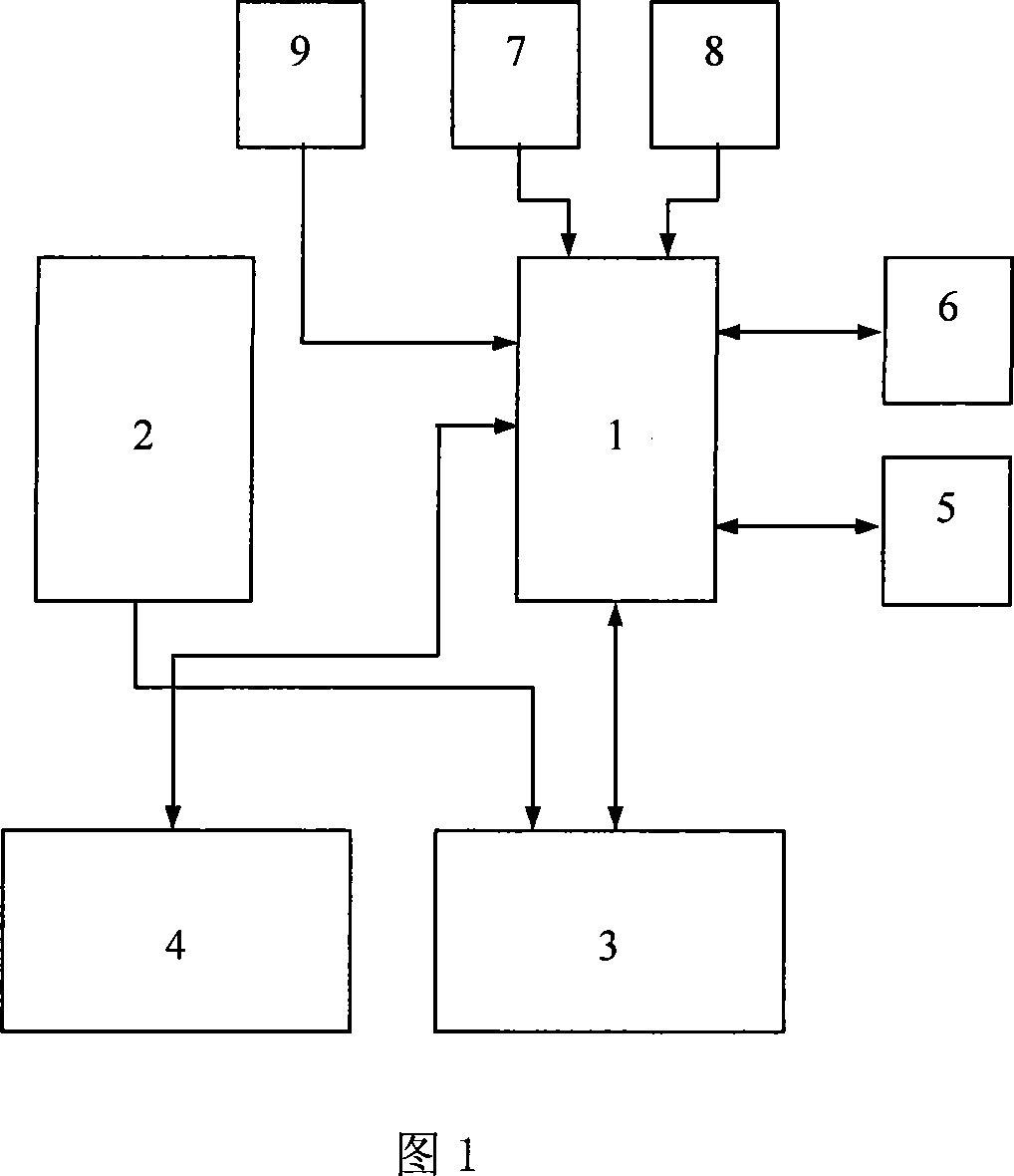
[0041] Referring to Fig. 1, the present invention is provided with main control module 1, clock control module 2, switch value control detection module 3, electric parameter detection module 4, cable anti-theft module 5, GPRS module 6, clock module 7, temperature acquisition module 8 and liquid crystal The display and key input module 9, the output end of the clock control module 2 is connected to the control end of the switching value control detection module 3, the control end of the switching value control detection module 3 is externally connected to the electromagnetic coil end of the AC contactor, and the detection end of the switching value control detection module 3 is externally connected AC contactor normally open and normally closed contacts, switch control detection module 3 communication end is connected to the I / O port of the main control module 1, the input end of the electric parameter detection module 4 is externally connected to a current transformer, and the...


PUM


Abstract

The invention relates to a signal control device, in particular, a streetlight landscape light remote monitoring device. The working condition of all streetlight sites is polled in real time through the real-time monitoring of a streetlight landscape light remote monitoring terminal based on GPRS technique. When the streetlight sites fail, information about the failure can be rapidly transmitted to the monitoring center and processed as warning; therefore, the failure can be solved. When a telephone cable is cut and stolen, warning can be given to the monitoring center. A main control module, a switching value control detection module and a GPRS module are provided. The main control module is provided with a microprocessor, a power module and a time clock module. The communication terminal of the time clock module is connected with an I/O port. The control terminal of the switching value control detection module is axially connected with the electromagnetic coil terminal of an alternating current contactor. The detection terminal of the switching value control detection module is axially connected with the normally open and normally close contacting point of the alternating current contactor. The communication terminal of the switching value control detection module is connected with the I/O port of the microprocessor. The communication terminal of the GPRS module is connected with an asynchronous serial interface of the microprocessor.

Description

technical field [0001] The invention relates to a signal control device, in particular to a device for remote monitoring of street lamp landscape lamps using GPRS communication technology. Background technique [0002] Street lamps and landscape lights are the symbol of the city's image, the window of the city, and the necessary public infrastructure in urban construction. Urban lighting is an important link related to the immediate interests of citizens, directly reflecting the level of urban construction and city appearance, and the level of control and management of street lights and landscape lights shows the degree of modernization of the city. my country's current street lamp landscape lamp monitoring system is still relatively backward in technology in general. Because the traditional lighting control method of street lights and landscape lights has no remote data collection and communication functions, it cannot realize centralized monitoring, so its operation and o...

Claims


Application Information

Patent Timeline
IPC IPC(8): G08C17/00G08C19/00H05B37/02
CPCY02B20/42Y02B20/72Y02B20/40
Inventor 刘暾东周文博郑中杰赵彬吕洪达
Owner XIAMEN INGOL DIGITAL TECH
Why Eureka
Try Eureka