
Positioning device for a color measuring head

A technology of positioning device and measuring head, which is applied in the direction of measuring device, machine/structural component testing, printing, etc., and can solve the problem of not being able to provide individual measurement positions

Active Publication Date: 2011-05-18
HEIDELBERGER DRUCKMASCHINEN AG
View PDF1 Cites 0 Cited by
  • Summary
  • Abstract
  • Description
  • Claims
  • Application Information

AI Technical Summary

Problems solved by technology

[0003] But the method in EP 13 88 418 B1 does not offer the possibility of selecting individual measuring positions after the event, in addition to transferring the measuring positions from the printing stage to the measuring device
If the printer also wants to select individual measurement positions on the gauge itself, he cannot do it this way

Method used


Image

  • Positioning device for a color measuring head
  • Positioning device for a color measuring head
  • Positioning device for a color measuring head

Examples


Embodiment Construction

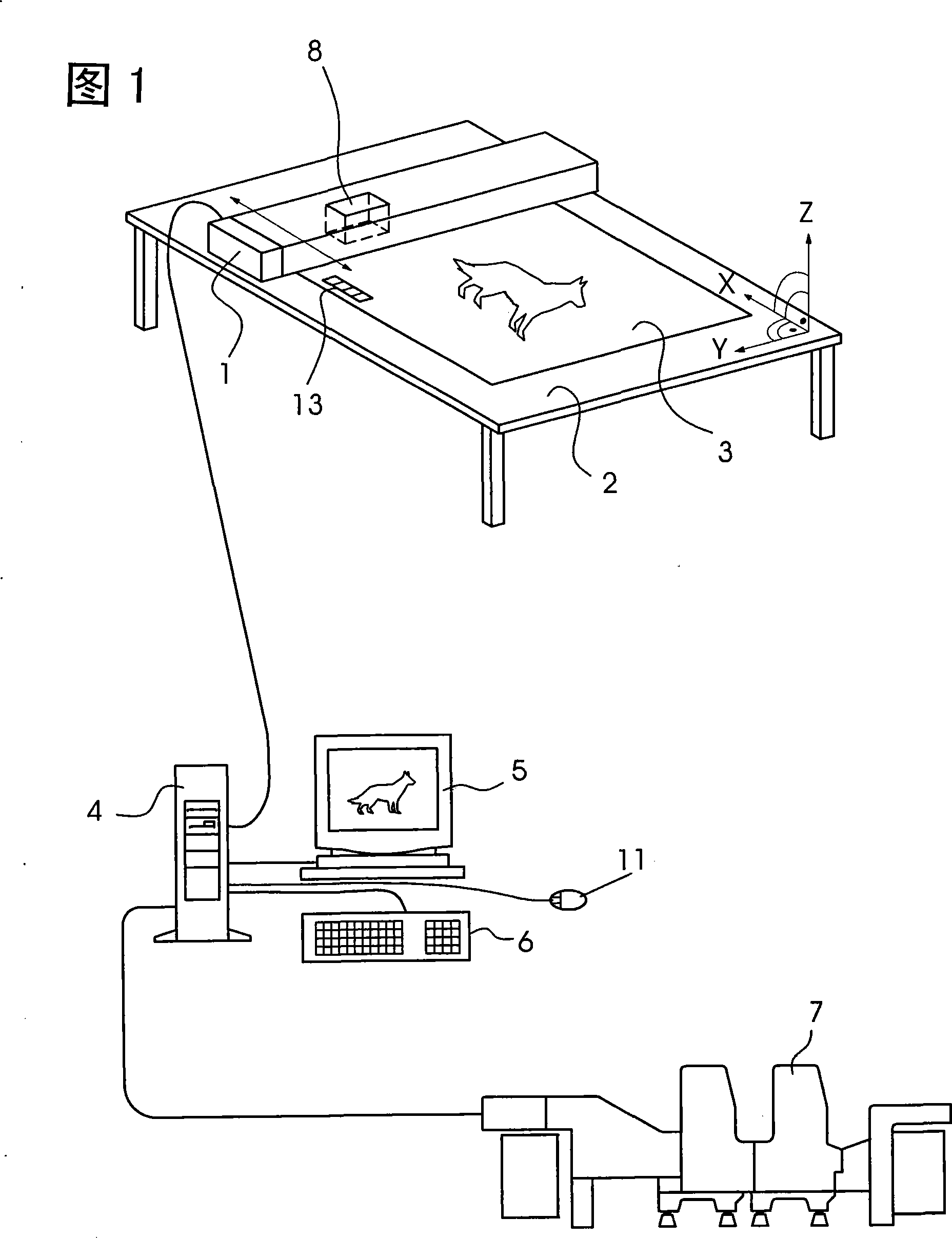
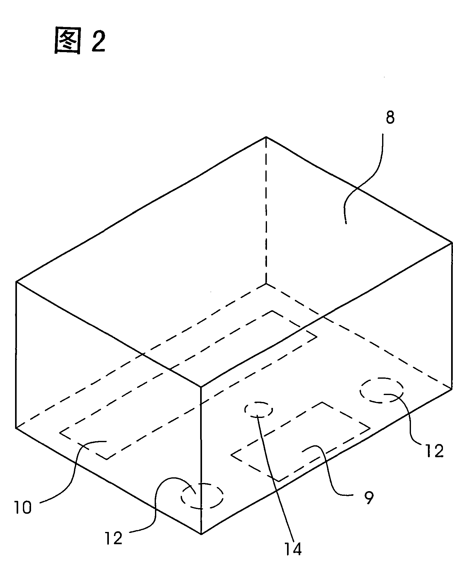
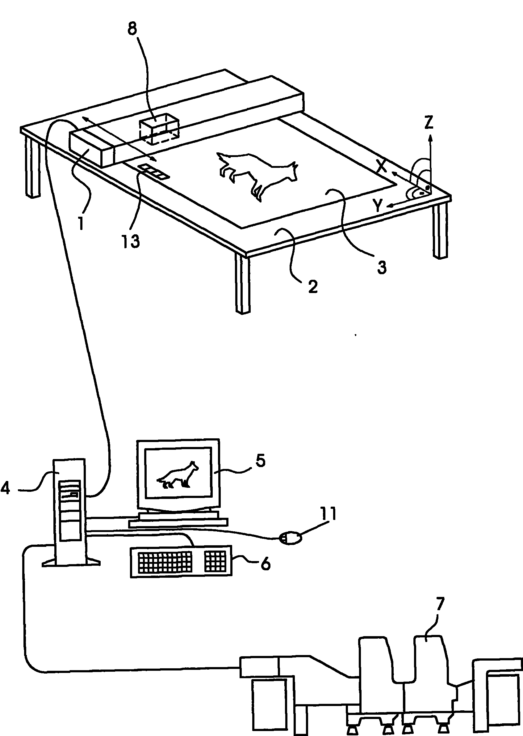
[0016] FIG. 1 shows a color measuring device which is connected to a computer 4 . The color measuring device consists of a measuring table 2 on which a produced printing material 3 can be placed. The placed printing material 3 can be measured, for example with respect to color, by means of the measuring beam 1 . The measuring beam 1 is displaceable in the X direction in FIG. 1 in order to be able to traverse the entire length of the deposited printing material 3 . The measuring beam 1 in turn has a measuring head 8 that can be moved in the Y direction, by means of which it can be moved in a targeted manner to individual measuring points on the printing material 3 in order to measure these measuring points with regard to color. Furthermore, for example, a color measuring strip 13 on the printing material 3 can be detected, detected and measured by means of the measuring head 8 . The data sensed by the measuring head 8 are sent to the computer 4 and can be represented on a dis...


PUM


Abstract

A device for positioning a measuring head above a print substrate includes a display device and a motor-driven positioning device for the measuring head. The motor-driven positioning device for the measuring head is controllable by a computer connected to the display device. Measurement locations are selectable on the display device and the measuring head is positioned by the positioning device depending on the selected measurement locations.

Description

technical field [0001] The invention relates to a device for positioning a measuring head over a printing material, with a display device and a motor-driven positioning device for the measuring head, wherein the positioning device for the measuring head can be controlled by a computer, the computer and The display device is connected. Background technique [0002] In order to check the quality of the printed matter produced by the printing press, it is necessary to remove and evaluate test sheets at regular intervals. In this case, an objective assessment is only possible with measuring devices which measure the color of the test sheet on the one hand and determine the register deviation on the other hand. Color measuring instruments and register measuring instruments are known from the prior art for this purpose. After the test sheet has been removed from the delivery stack of the printing press, it is placed on a support table and connected, for example, by a color measu...

Claims


Application Information

Patent Timeline
Patent Type & Authority Patents(China)
IPC IPC(8): H04N1/60B41F33/02B41F33/00G01M99/00H04N1/46
CPCB41F33/0036
Inventor H·恩格勒W·胡贝尔M·施奈德V·贝克尔
Owner HEIDELBERGER DRUCKMASCHINEN AG
Learn More