Movable tank structure for air regulating device
An air-conditioning and movable technology, which is applied in the field of component structures, can solve problems such as incompleteness, inconvenient cleaning of the water tank, troublesome and inconvenient extraction and insertion of the water tank, and achieve the effect of convenient insertion
- Summary
- Abstract
- Description
- Claims
- Application Information
AI Technical Summary
Problems solved by technology
Method used
Image
Examples
Embodiment 1
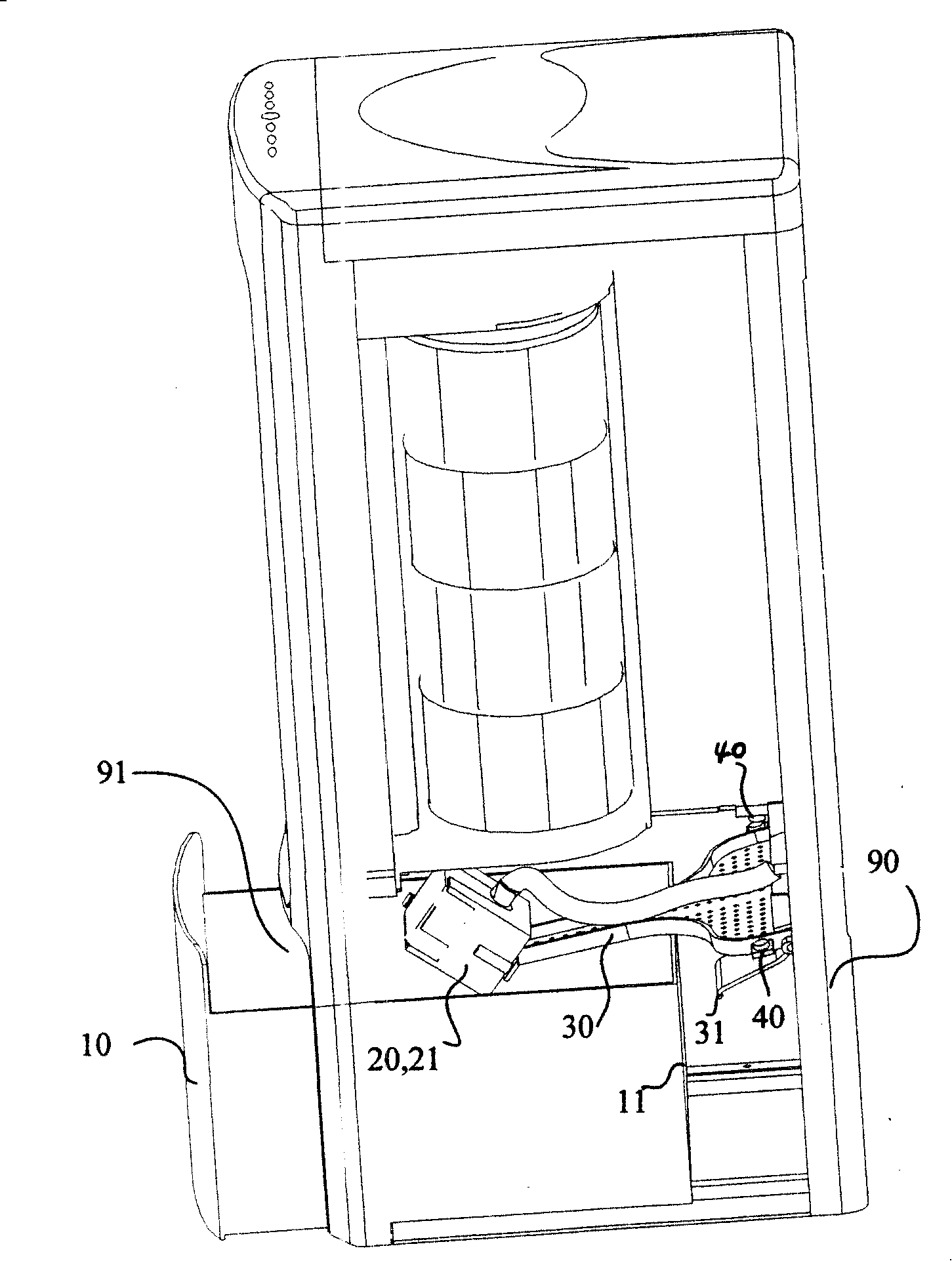
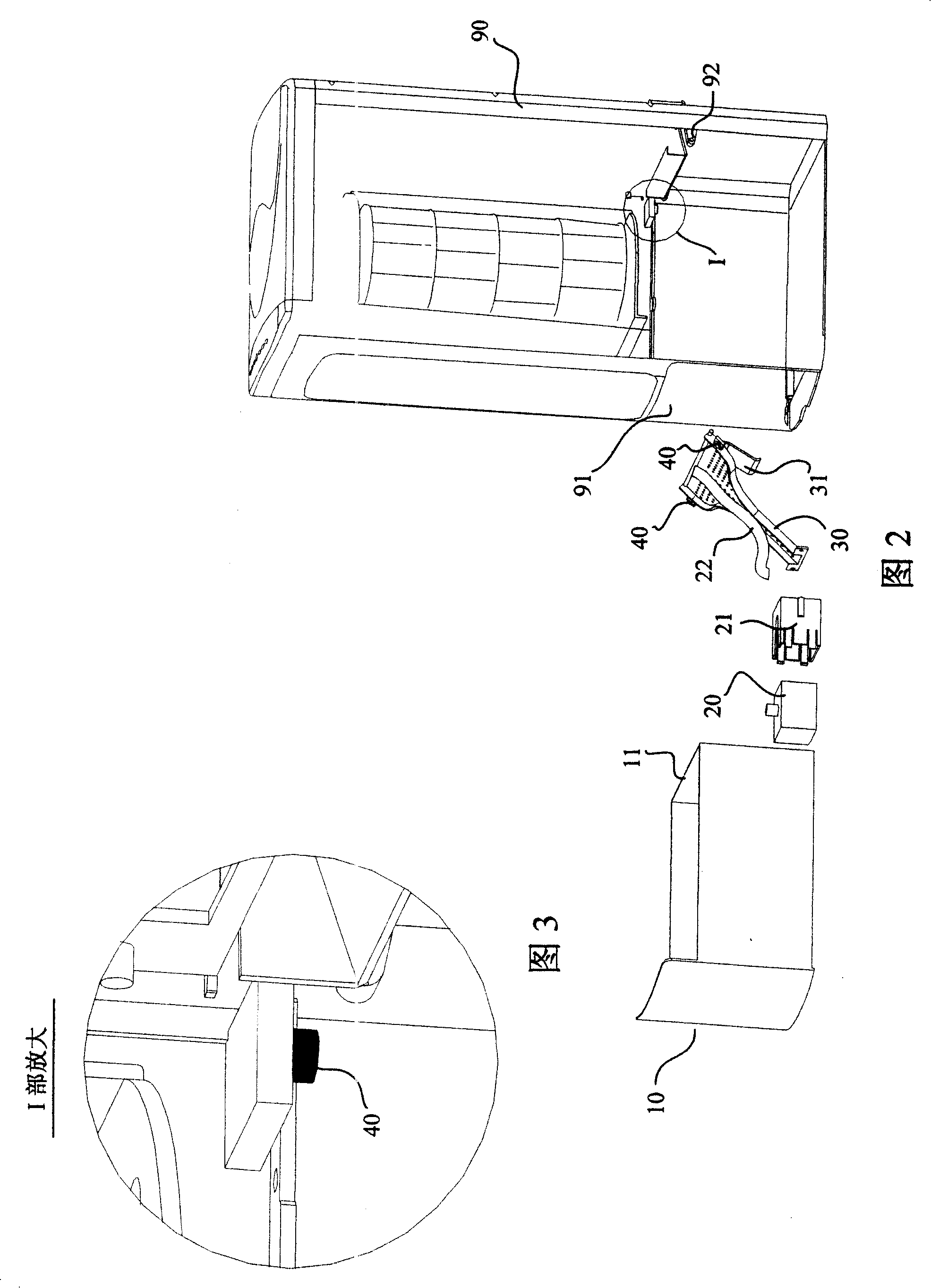
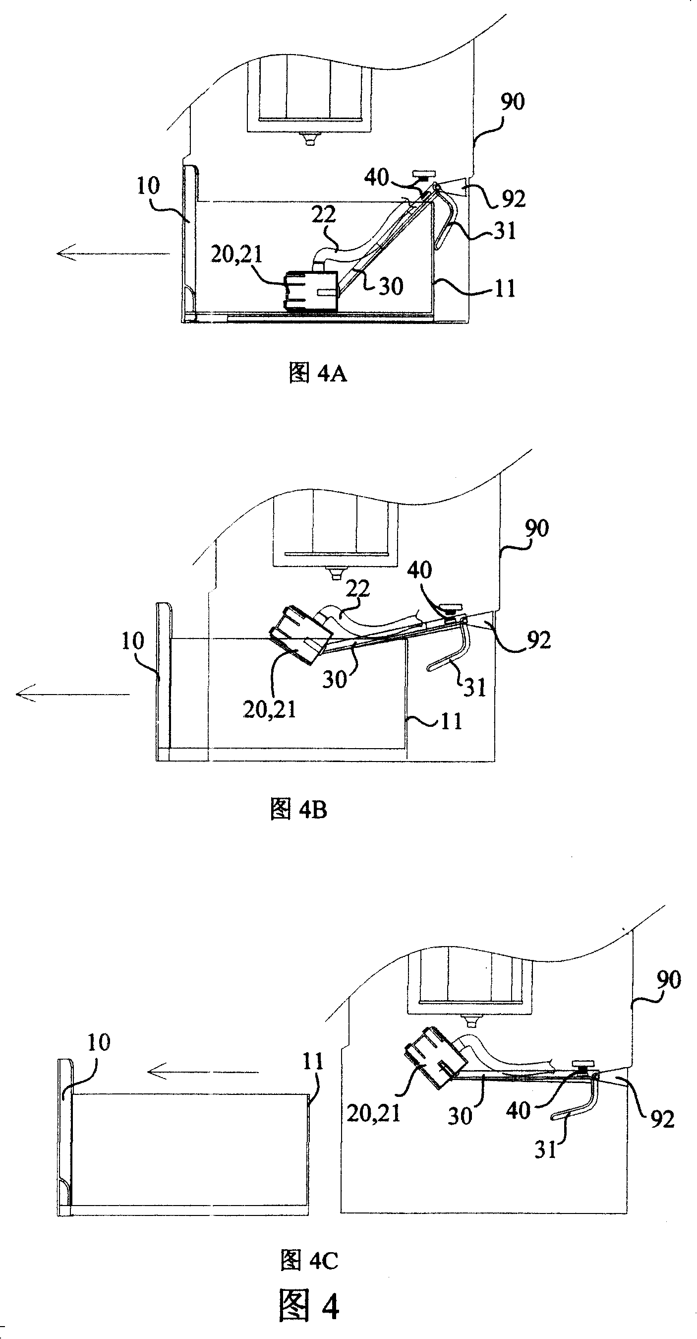
[0024] The present invention is used for the movable water tank structure of air conditioner, as figure 1 2 includes the water tank 10 placed in the housing 90 of the air conditioning device and the opening 91 provided on the housing 90 for the water tank 10 to be drawn out or pushed in. The opening 91 is opened at the lower front or rear of the housing 90 Below, the submersible pump 20 and the submersible pump housing 21 are placed in the water tank 10, and the outlet pipe 22 of the submersible pump 20 leads the water in the water tank to the top of the housing; it also includes a submersible pump positioning frame 30 and a positioning frame fixing Seat 92, the positioning frame fixing seat 92 is arranged in the housing 90, one end of the positioning frame 30 is connected and fixed with the submersible pump casing 21, and the other end of the positioning frame 30 is rotatably connected with the positioning frame fixing seat 92 by means of a pin shaft; A magnetic assembly 40 i...
Embodiment 2
[0030] The solution of the second embodiment is basically the same as that of the first embodiment, except that the stretchable elastic member 50 is used to realize the function of the magnetic component 40 or the elastic buckle component in the first embodiment. In this embodiment, the stretchable elastic member 50 is a coil spring 50 .
[0031] A movable water tank structure for an air conditioning device, as shown in Figure 6, includes a water tank 10 placed in the housing 90 of the air conditioning device and a water tank 10 set on the housing 90 for pulling out or pushing in The opening 91 is opened in the front or rear of the housing 90, the submersible pump 20 and the submersible pump housing 21 are placed in the water tank 10, and the outlet pipe 22 of the submersible pump 20 leads the water in the water tank to the housing It also includes a submersible pump positioning frame 30 and a positioning frame fixing seat 92, the positioning frame fixing seat 92 is arranged i...
Embodiment 3
[0036] The solution of the third embodiment is basically the same as that of the second embodiment, except that in this embodiment, the stretchable elastic member is a leaf spring, while the stretchable elastic member in the second embodiment is a coil spring.
[0037] As shown in Figure 9, relative to the submersible pump 20, the leaf spring 51 is installed on the other side of the rotation center of the positioning frame 30, that is, the fixing seat 92, and the two ends of the leaf spring 51 are respectively connected to the positioning frame 30. The tail is connected with the housing 90 . As shown in FIG. 9A, when the water tank 10 is not pushed into the housing 90, the leaf spring 51 is opened, and the elastic force of the leaf spring 51 is used to support the positioning frame 30 and the submersible pump 20 remains suspended in the air, so that the water tank 10 Push it smoothly into the housing 90; as shown in Figure 9B, when the water tank 10 is fully pushed into the ho...
PUM
 Abstract
Description
Claims
Application Information
 - R&D
- Intellectual Property
- Life Sciences
- Materials
- Tech Scout
- Unparalleled Data Quality
- Higher Quality Content
- 60% Fewer Hallucinations
Browse by: Latest US Patents, China's latest patents, Technical Efficacy Thesaurus, Application Domain, Technology Topic, Popular Technical Reports.
© 2025 PatSnap. All rights reserved.Legal|Privacy policy|Modern Slavery Act Transparency Statement|Sitemap|About US| Contact US: help@patsnap.com


