Heat pipe and its manufacturing method

A manufacturing method and heat pipe technology, applied in the field of flat heat pipes and their manufacturing, can solve the problems of lack of support force, bending or depression in local areas, affecting the heat conduction efficiency of flat heat pipes, etc.

Inactive Publication Date: 2008-04-16
DELTA ELECTRONICS INC
View PDF0 Cites 11 Cited by
  • Summary
  • Abstract
  • Description
  • Claims
  • Application Information

AI Technical Summary

Problems solved by technology

On the inner wall of the upper plate 12 and the lower plate 14, a capillary structure 15 is formed, but the disadvantage of this existing welding method of the upper and lower plates is that it prevents the solder from overflowing into the inner walls of the upper and lower plates when welding, so the upper and lower plates 12, There will be a capillary discontinuous area 121, 141 formed on the inner wall of 14, which will not only interrupt the heat conduction path in the heat pipe, but also affect the heat conduction efficiency in the flat heat pipe
[0005] Traditionally, the upper and lower plates are welded together, not only the welding path is long a

Method used


Image

  • Heat pipe and its manufacturing method
  • Heat pipe and its manufacturing method
  • Heat pipe and its manufacturing method

Examples


Embodiment Construction

[0044] Embodiments of the heat dissipation module and the heat pipe thereof according to the present invention will be described below with reference to related drawings.

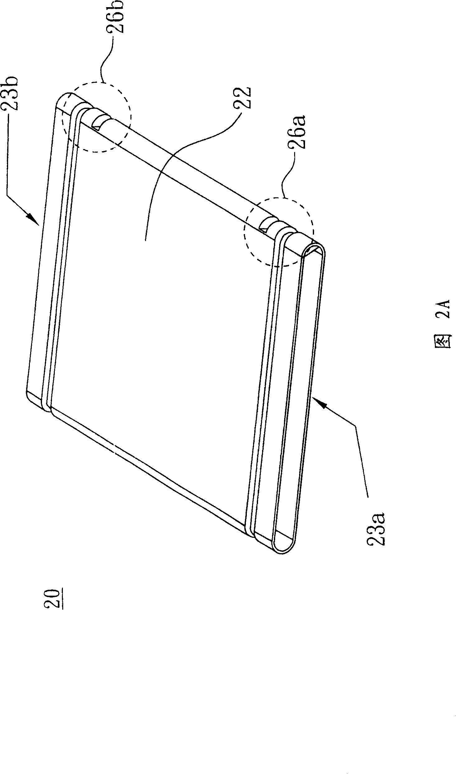
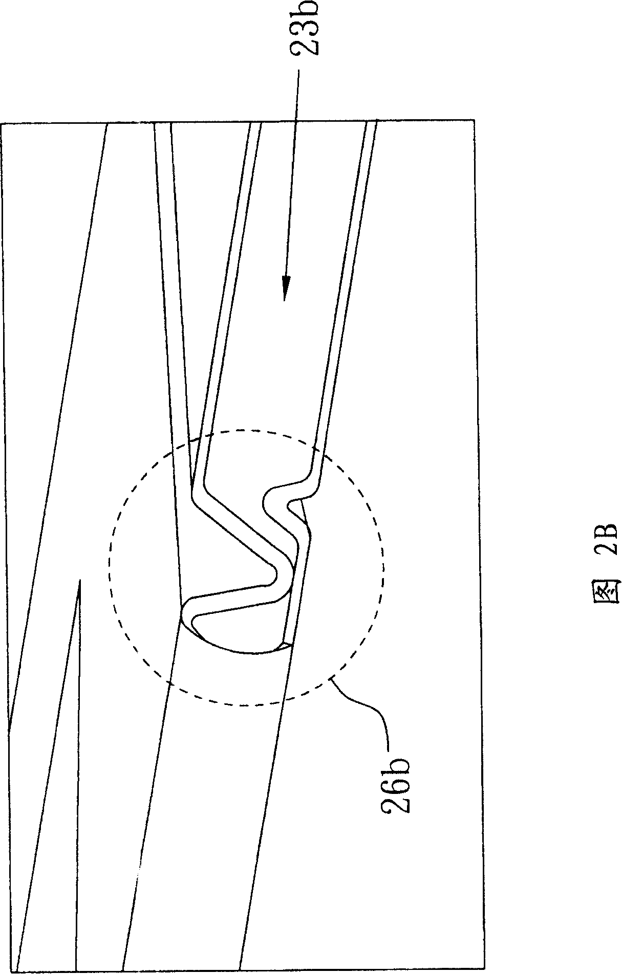
[0045] Please refer to FIG. 2A and FIG. 2C at the same time. FIG. 2A is a schematic diagram of a flat heat pipe according to a preferred embodiment of the present invention, and FIG. 2C is a schematic cross-sectional view of the flat heat pipe in FIG. 2A . In Fig. 2A, the planar heat pipe 20 includes a flat hollow ring body 22, which has two open ends 23a, 23b, and a capillary structure 25 is formed on the inner wall surface of the hollow ring body 22, wherein the two open ends 23a, 23b are closer Each has a bending portion 26a, 26b, so that the hollow ring body 22 forms a closed space 27, and a working fluid 28 is filled in the closed space 27.

[0046] Next, please refer to FIG. 2A and FIG. 2B , FIG. 2B is an enlarged view of the bending portion in FIG. 2A . The hollow ring body 22 is integrally formed b...


PUM


Abstract

The invention discloses a plate-type heat tube and a method for manufacturing the same. The plate-type heat tube comprises a flat hollow ring body which is provided with two opening ends, and the surface of the inner wall of the hollow ring body forms a capillary structure, wherein, a bending part is also provided next to the two opening ends and causes the hollow ring body to form airtight space, and working fluid is filled in the airtight space.

Description

technical field [0001] The invention relates to a heat pipe and its manufacturing method, in particular to a flat heat pipe with low cost but high efficiency and its manufacturing method. Background technique [0002] With the development of science and technology, the number of transistors per unit area of ​​electronic components is increasing, resulting in an increase in heat generation during use. Since a heat pipe is a simple but extremely effective heat dissipation device, it has been widely used in various electronic heat dissipation products. Its working principle is to transfer energy through the latent heat of the phase change between the gas and liquid phases of the working medium. In the evaporation section (vaporization section), the working fluid takes away a large amount of heat energy from the heat source by means of the latent heat of evaporation, and its vapor fills the inner space of the tube that has been evacuated and condenses into a liquid in the conde...

Claims


Application Information

Patent Timeline
IPC IPC(8): F28D15/04
Inventor 庄明德林祺逢陈锦明
Owner DELTA ELECTRONICS INC
Why Eureka
Try Eureka