
Liquid crystal display board and LCD

A technology for liquid crystal display panels and substrates, which is applied to instruments, nonlinear optics, optics, etc., can solve problems such as the influence of the wide viewing angle display effect of liquid crystal display panels, and achieve the effect of improving display quality.

Active Publication Date: 2008-04-16
AU OPTRONICS CORP
View PDF0 Cites 7 Cited by
  • Summary
  • Abstract
  • Description
  • Claims
  • Application Information

AI Technical Summary

Problems solved by technology

However, due to the trend of high resolution, the pixel unit of the liquid crystal display panel becomes smaller, and the design of the thin slit is also relatively limited due to the limited area and process capability of the pixel electrode, such as the alignment direction of the thin slit on the pixel electrode It will be reduced accordingly, and the wide viewing angle display effect of the liquid crystal display panel will be affected

Method used


Image

  • Liquid crystal display board and LCD
  • Liquid crystal display board and LCD
  • Liquid crystal display board and LCD

Examples


Embodiment Construction

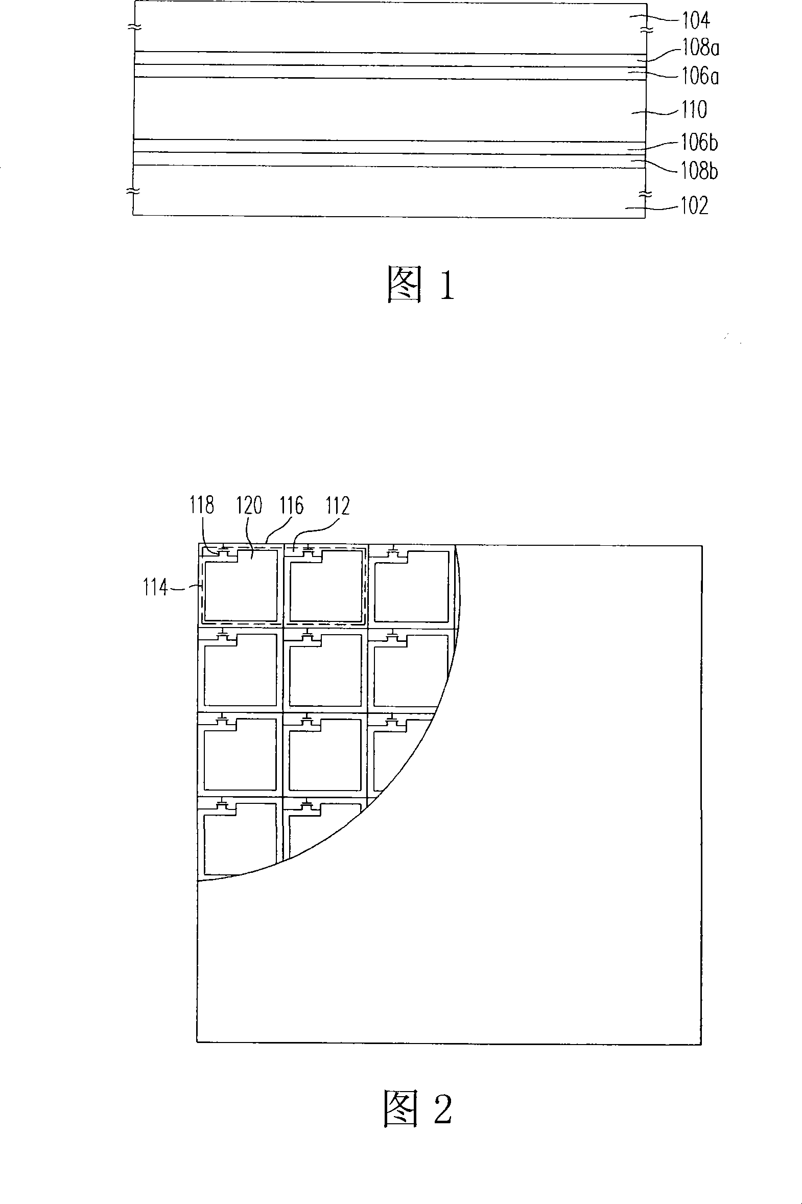
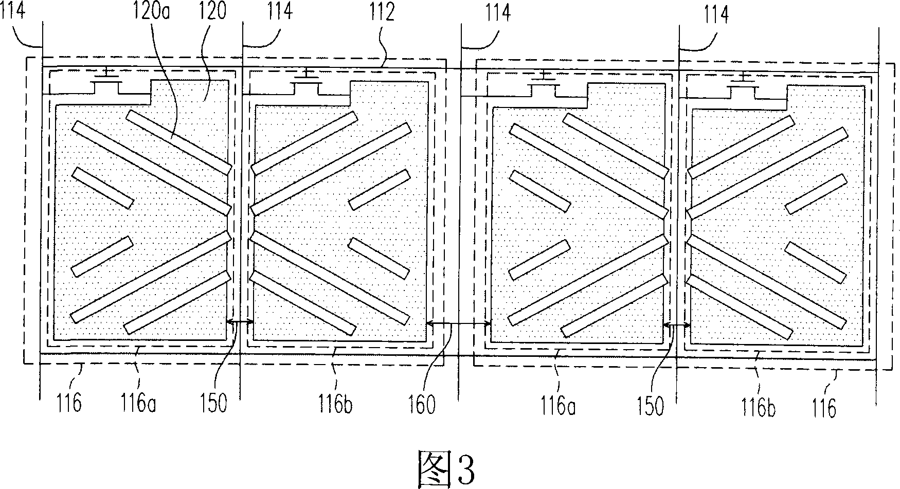
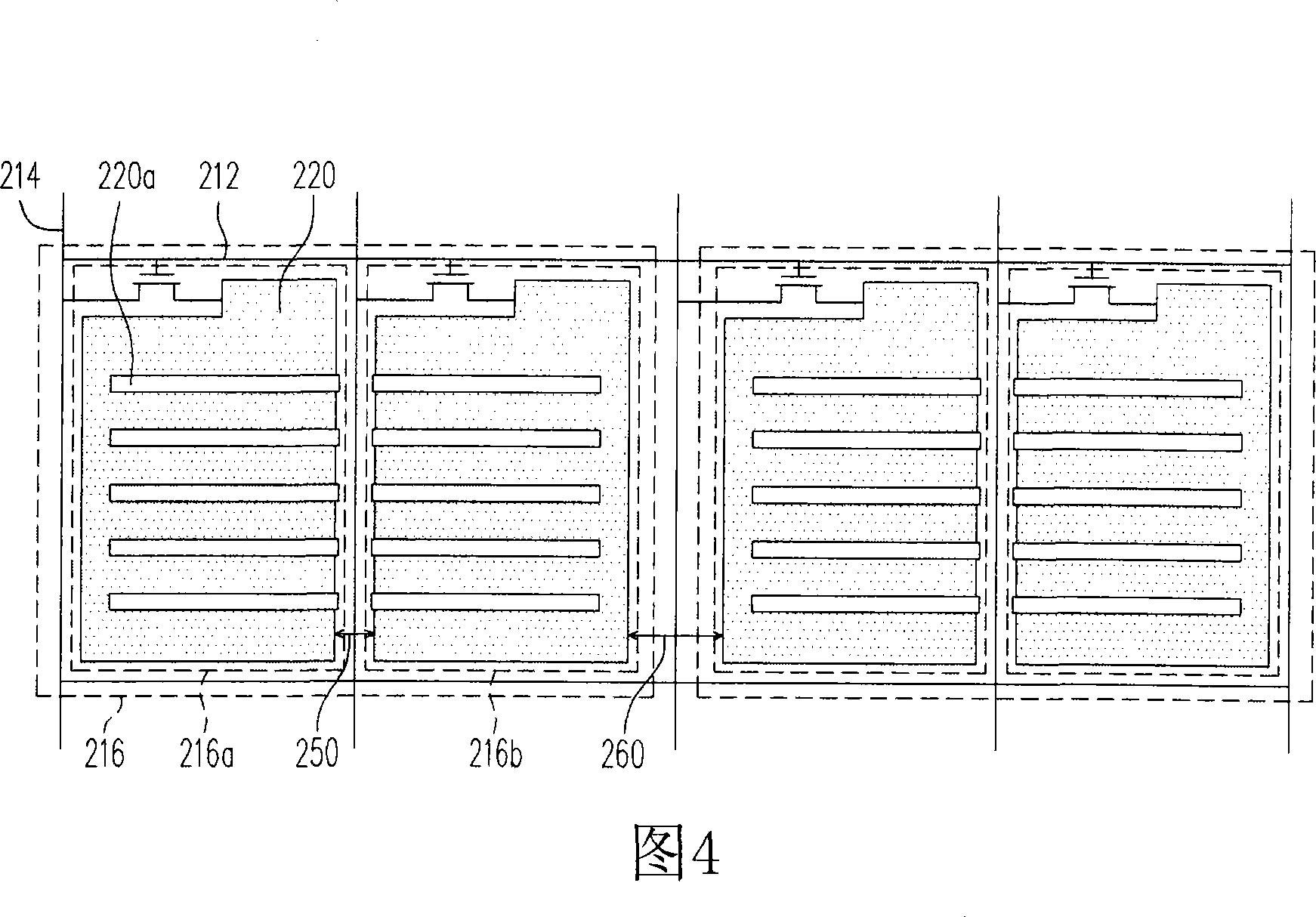
[0050] The present invention can be applied to a liquid crystal display panel produced by a polymer stable alignment process, wherein multiple pixel unit groups are divided by designing the width of the main slit between the pixel units, and different pixels in the same pixel unit group The thin slits of the units are designed to achieve the effect of multi-region alignment in the polymer stable alignment process through the combination of pixel units. In more detail, although the design of the thin slits on the pixel electrode will be limited due to the limited area of ​​the pixel electrode and the limit of process capability, resulting in a reduction in the number or alignment direction of the thin slits in a single pixel unit, the present invention Multiple pixel units can be combined to obtain the desired alignment effect. In other words, the design of the present invention can provide a relatively high design latitude of thin slits under the requirement of high resolution...


PUM


Abstract

The invention discloses a liquid crystal display panel and a liquid crystal display. The panel comprises a first base plate, a second base plate, a plurality of scanning beams, a plurality of data wires, a plurality of pixel unit groups, and at least one polymer layer and a liquid crystal layer. The scanning beams, the data wires and the pixel unit groups are arranged on the first base plate and each pixel unit group comprises a plurality of pixel units, wherein, a first main gap is arranged between every two adjacent pixel unit groups, a second main gap is arranged between every two adjacent pixel units in each pixel unit group, and each pixel unit comprises an initiative element and a transparent pixel electrode. The initiative elements are electrically connected with the scanning beams and the data wires. The transparent pixel electrodes are electrically connected with the initiative elements and have a plurality of small gaps. The polymer layer is arranged on the surface of the first base plate or the second base plate. Furthermore, each first main gap is wider than each second main gap.

Description

technical field [0001] The present invention relates to a liquid crystal display panel and a liquid crystal display, in particular to a liquid crystal display panel utilizing polymer-stabilized alignment. Background technique [0002] With the substantial improvement of computer performance and the high development of Internet and multimedia technology, the volume of video or imaging devices tends to be thinner and thinner day by day. In the development of displays, with the advancement of optoelectronic technology and semiconductor manufacturing technology, liquid crystal displays with superior characteristics such as high image quality, good space utilization efficiency, low power consumption, and no radiation have gradually become the mainstream of the market. [0003] The liquid crystal display includes a backlight module and a liquid crystal display panel, while a traditional liquid crystal display panel is composed of two substrates and a liquid crystal layer filled be...

Claims


Application Information

Patent Timeline
IPC IPC(8): G02F1/1362G02F1/1337G02F1/1343
Inventor 陈映如林敬桓张志明
Owner AU OPTRONICS CORP
Learn More