Programmable gain amplifier and method

A technology for programming gain and amplifiers, which is applied in the direction of gain control, amplification control, and control of components of amplification devices, etc., which can solve the problems of increasing the chip area of ​​circuit components and power consumption.

Inactive Publication Date: 2008-04-16
TEXAS INSTR INC
View PDF0 Cites 9 Cited by
  • Summary
  • Abstract
  • Description
  • Claims
  • Application Information

AI Technical Summary

Problems solved by technology

The result is an undesired increase in circuit components and (thus) chip area and power consumption

Method used


Image

  • Programmable gain amplifier and method
  • Programmable gain amplifier and method
  • Programmable gain amplifier and method

Examples


Embodiment Construction

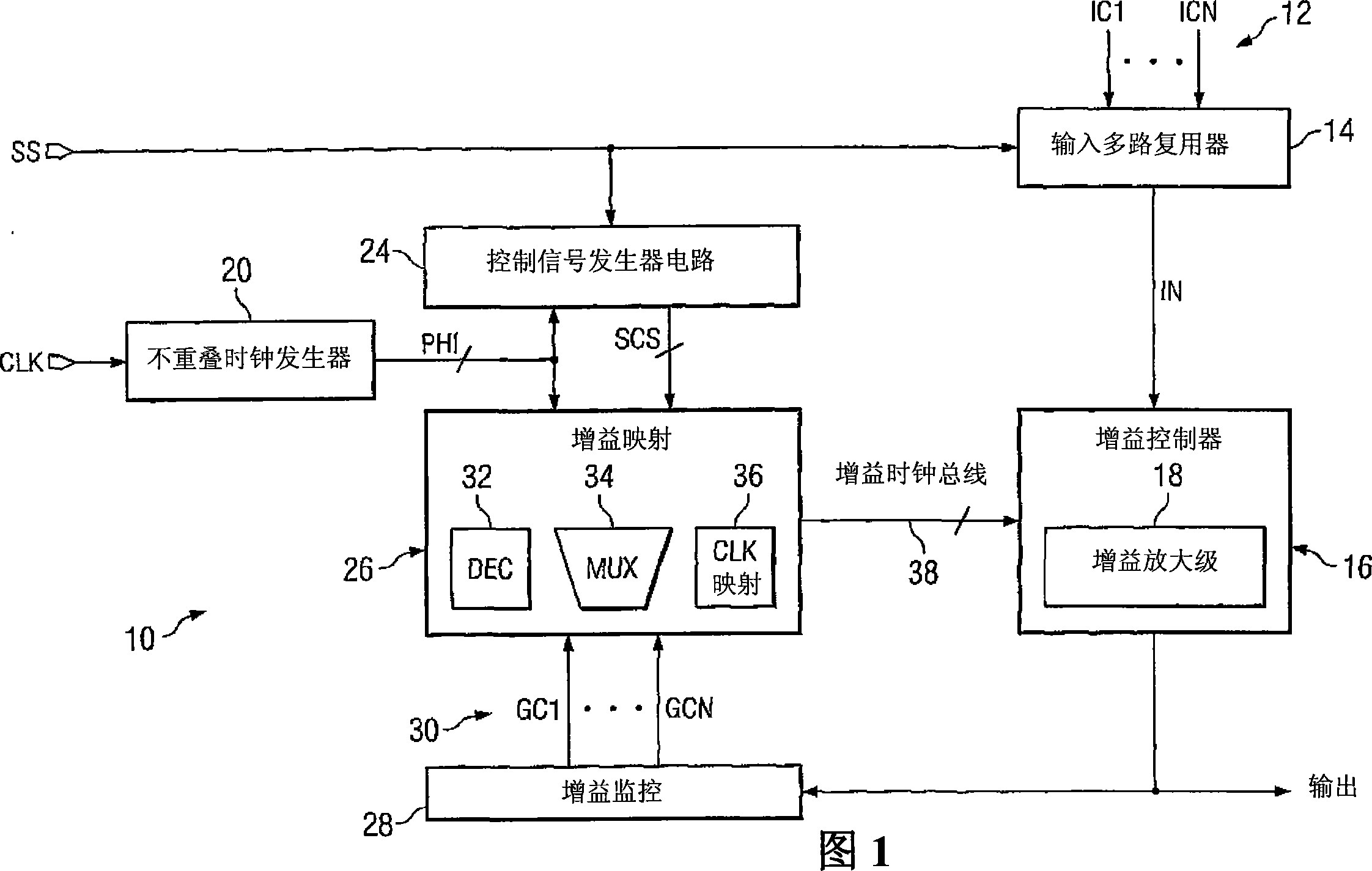
[0016] The present invention relates to electronic circuits, and more particularly to amplifying one or more analog input signals in a programmable gain amplifier. The programmable gain amplifier may include an input multiplexer operable to sequentially select an input signal for amplification from a plurality of input signals based on a selection signal. The select signal cycles through all of the input signals at timed intervals. The programmable gain amplifier may also include at least one amplifier gain stage operable to apply a variable amount of gain to a selected input signal. A variable amount of gain applied to a selected input signal can be controlled by a gain mapping component so that the same or a different amount of gain can be applied to each of the plurality of input signals.

[0017] FIG. 1 illustrates a programmable gain amplifier system 10 according to one aspect of the present invention. Amplifier system 10 is capable of providing amplification of a numbe...


PUM


Abstract

One embodiment of the invention may include a programmable gain amplifier comprising an input multiplexer (14) operative to sequentially select input signals (12) for amplification. The input signals may be chosen from a plurality of input signals based on a selection signal. The programmable gain amplifier (18) may include at least one amplifier gain stage operative to apply a variable gain amount to a selected input signal. The programmable gain amplifier may further include a gain mapping component that controls the variable gain amount for each of the selected input signals.

Description

technical field [0001] The present invention relates to electronic circuits, and more particularly to a programmable gain amplifier and method. Background technique [0002] In analog signal processing applications, such as in automotive, wireless communications, or networking applications, it is often necessary to amplify the input analog signal before it can be processed. Amplifying the input analog signal is necessary for optimal processing and usually involves passing the input signal through an amplifier. [0003] A Programmable Gain Amplifier (PGA) is a circuit that allows an input signal to be boosted to a programmed optimized gain level. The PGA can be single-stage (for low-speed applications requiring only coarse gain control) or multi-stage (for high-speed applications requiring fine gain control). However, a PGA operating at high speed consumes more power. Thus, there are competing design constraints between operating speed and power consumption in a PGA. Addi...

Claims


Application Information

Patent Timeline
Patent Type & Authority Applications(China)
IPC IPC(8): H03G3/30
CPCH03G3/008H03G3/3036H03G1/0088
Inventor 穆罕默德·A·阿尔-夏伊奥克亚历山大·托伊奇
Owner TEXAS INSTR INC
Why Eureka
Try Eureka