Precision lifting device

A precise and driving device technology, applied in the direction of lifting device, lifting frame, etc., can solve the problems of large focusing and leveling components and limited installation space, and achieve the effect of large lifting height, stable lifting and high resolution of height value

Inactive Publication Date: 2008-04-23
SHANGHAI MICRO ELECTRONICS EQUIP (GRP) CO LTD
View PDF1 Cites 11 Cited by
  • Summary
  • Abstract
  • Description
  • Claims
  • Application Information

AI Technical Summary

Problems solved by technology

The focusing and leveling part is a precision measuring part. During the installation process, there should be no large vibration. There are many precision parts installed around it, but the focusing and leveling part itself is relatively large, and the installation space is limited. Therefore, it is required that the tooling can move and rotate flexibly and freely, and can be fixed quickly after reaching the positioning point without mechanical connection. However, the current lifting devices cannot meet such requirements.

Method used


Image

  • Precision lifting device
  • Precision lifting device

Examples


Embodiment Construction

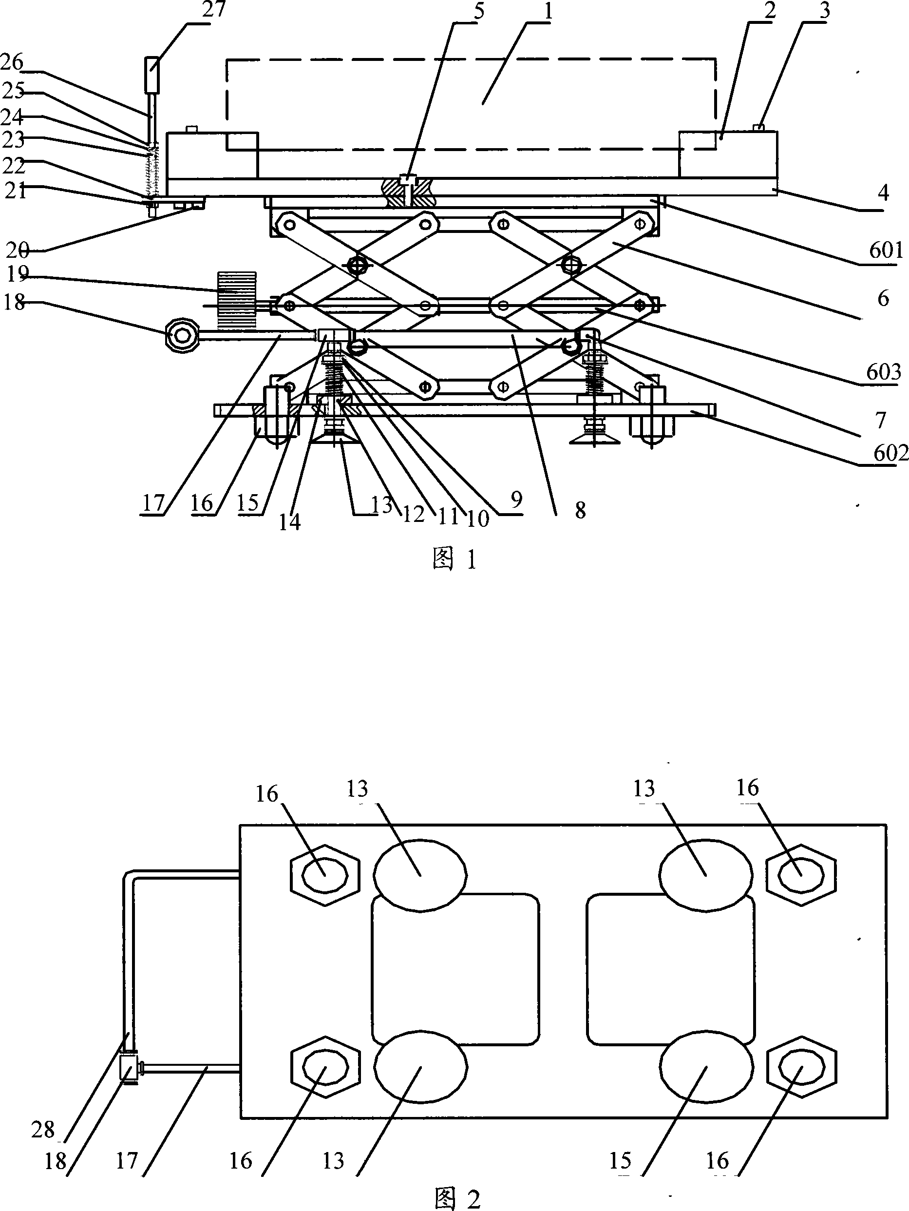
[0021] Below in conjunction with the accompanying drawings, a precision lifting device of the present invention will be further described:

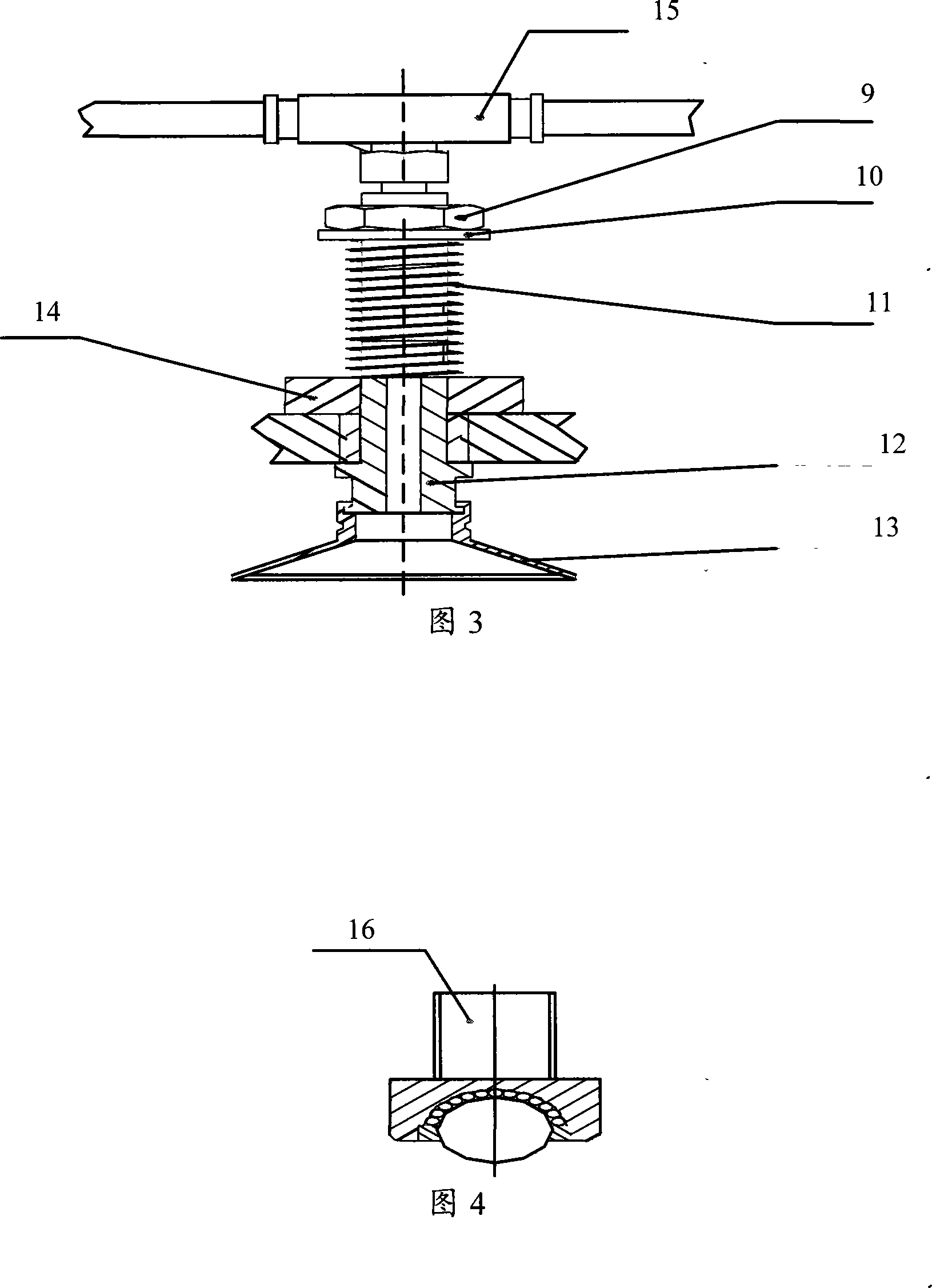
[0022] As shown in Fig. 1, the present invention includes a positioning block 2, a bearing plate 4, a lifting mechanism 6, a steel ball roller mechanism 16, a hand wheel 19, a vacuum adsorption mechanism, and a height limiting mechanism.

[0023] Positioning block 2 utilizes screw 3 to be fixed on the two ends of bearing plate 4, and bearing plate 4 utilizes screw 5 to be installed on the upper panel 601 of lifting mechanism 6, and the height limiting mechanism is fixed on one end of bearing plate 4.

[0024] The lifting mechanism 6 is composed of more than two lifting units connected in parallel, the lifting units are connected by two X-shaped trusses through hinges, and the driving device is assembled at the joints of the hinges.

[0025] Wherein the height limiting mechanism comprises: a spring 23, a gasket 24, a nut 25, a screw rod 26...


PUM


Abstract

The present invention relates to a precision lifting equipment. It includes the following several portions: bearing plate, lifting mechanism, upper panel, lower panel and driving device, in which the lifting mechanism is composed of more than two lifting units which are parallelly connected, the described lifting unit is formed from two X-type girders which are connected by means of hinge. The described driving device is assembled in the connected position of the described hinge. Said invention can be used for mounting and lifting precision apparatus and instrument.

Description

technical field [0001] The invention relates to a lifting device, in particular to a lifting device installed with precision instruments. Background technique [0002] For the scissor lift table, the minimum height itself is generally small, but in actual work it is often necessary to lift a larger height, so the overall size is generally relatively large, which will reduce the lifting accuracy. At the same time, there will be greater vibration when lifting, so it cannot be used to lift high-precision equipment. Moreover, the entire lifting platform cannot move and rotate flexibly. During the entire lifting process, there is no height limit mechanism, and it is completely dependent on visual inspection, so it is difficult to achieve accurate alignment. Regardless of whether the lifting method is manual, pneumatic, hydraulic, hydraulic or electric, the weight of the entire lifting platform is heavy and it is inconvenient to carry. [0003] Chinese patent CN2761570Y disclose...

Claims


Application Information

Patent Timeline
Patent Type & Authority Applications(China)
IPC IPC(8): B66F7/06B66F7/28
Inventor 肖可云袁志扬严天宏
Owner SHANGHAI MICRO ELECTRONICS EQUIP (GRP) CO LTD
Why Eureka
Try Eureka