A mobile water sound communication method

An underwater acoustic communication and communication channel technology, applied in electrical components, multi-frequency code systems, transmission systems, etc., can solve problems affecting performance and mismatch, and achieve the effect of improving communication speed

Inactive Publication Date: 2010-10-06
HARBIN ENG UNIV
View PDF2 Cites 0 Cited by
  • Summary
  • Abstract
  • Description
  • Claims
  • Application Information

AI Technical Summary

Problems solved by technology

[0003] Linear frequency modulated signal (LFM) is widely used in the field of underwater acoustics. When there is no Doppler frequency offset, the copy correlator is the best detector for LFM signal, but when there is frequency offset, mismatch will occur and affect the performance.

Method used


Image

  • A mobile water sound communication method
  • A mobile water sound communication method
  • A mobile water sound communication method

Examples


Embodiment Construction

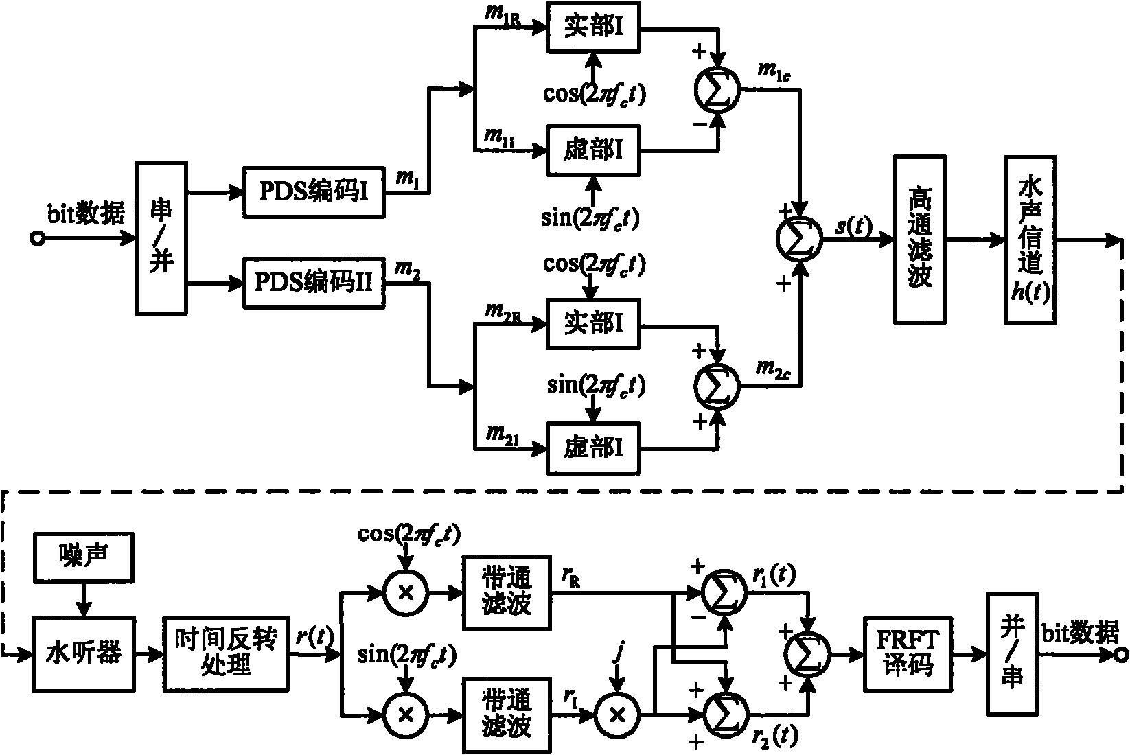
[0021] The present invention is described in more detail below in conjunction with accompanying drawing example:

[0022] In the present invention, two Patterns are selected in the communication frequency band, corresponding to two communication channels working at the same time. The encoded waveform of communication channel 1 can be expressed as:

[0023] m 1 ( t ) = Σ i = 0 + ∞ p attern 1 ( t - i · T 0 - k 1 i · Δτ ) , k 1 i = 0,1 ...


PUM


Abstract

This invention provides a mobile underwater communication method: 1, selecting LFM signal as a code shape of Pattern of a Pattern time delay difference coding system, in which, pattern1(t) of channel 1 is a positive LFM signal and pattern2(t) of channel 2 is a negative LFM signal, 2, carrying out time delay difference coding to channel 1 and 2, 3, carrying out orthogonal carrier modulation to thetwo channels and overlapping and emitting signals of the two channels, 4, multiplying the received signals with sine and cosine signals of the carrier frequency separately filtering HF components by a band pass filter, 5, constituting two paths of multiple signals and carrying out optimum stage fractional stage Fourier conversion, 6, measuring time delay values of the FRFT peak value separately on the u positive and negative half shaft of FRFT to decode to the two paths of communication channels.

Description

(1) Technical field [0001] The present invention relates to the field of underwater acoustic communication, more precisely, relates to a method for realizing mobile underwater acoustic communication. (2) Background technology [0002] The prospect of today's underwater acoustic communication is the underwater acoustic data communication network composed of active nodes and static nodes. Underwater acoustic communication will be very meaningful. [0003] Linear frequency modulated signal (LFM) is widely used in the field of underwater acoustics. When there is no Doppler frequency offset, the copy correlator is the best detector for LFM signal, but when there is frequency offset, mismatch will occur and affect the performance. Fractional Fourier transform has the characteristics of LFM base decomposition. When an LFM signal is selected in the fractional Fourier transform domain with an appropriate fractional order, it will appear as an impulse function, that is, the fractiona...

Claims


Application Information

Patent Timeline
Patent Type & Authority Patents(China)
IPC IPC(8): H04B13/02H04L27/26
Inventor 殷敬伟惠俊英
Owner HARBIN ENG UNIV
Why Eureka
Try Eureka