Metal halide lamp

A metal halide lamp and halide technology, which can be applied to discharge lamps, gas discharge lamps, parts of gas discharge lamps, etc., can solve the problems of low luminous efficacy and the like

Active Publication Date: 2008-04-23
SIGNIFY HLDG BV
View PDF1 Cites 0 Cited by
  • Summary
  • Abstract
  • Description
  • Claims
  • Application Information

AI Technical Summary

Problems solved by technology

However, due to the specific type of salt mixture used and the high reactivity of Al to the tungsten metal of the electrodes, this known lamp

Method used


Image

  • Metal halide lamp
  • Metal halide lamp

Examples


Embodiment Construction

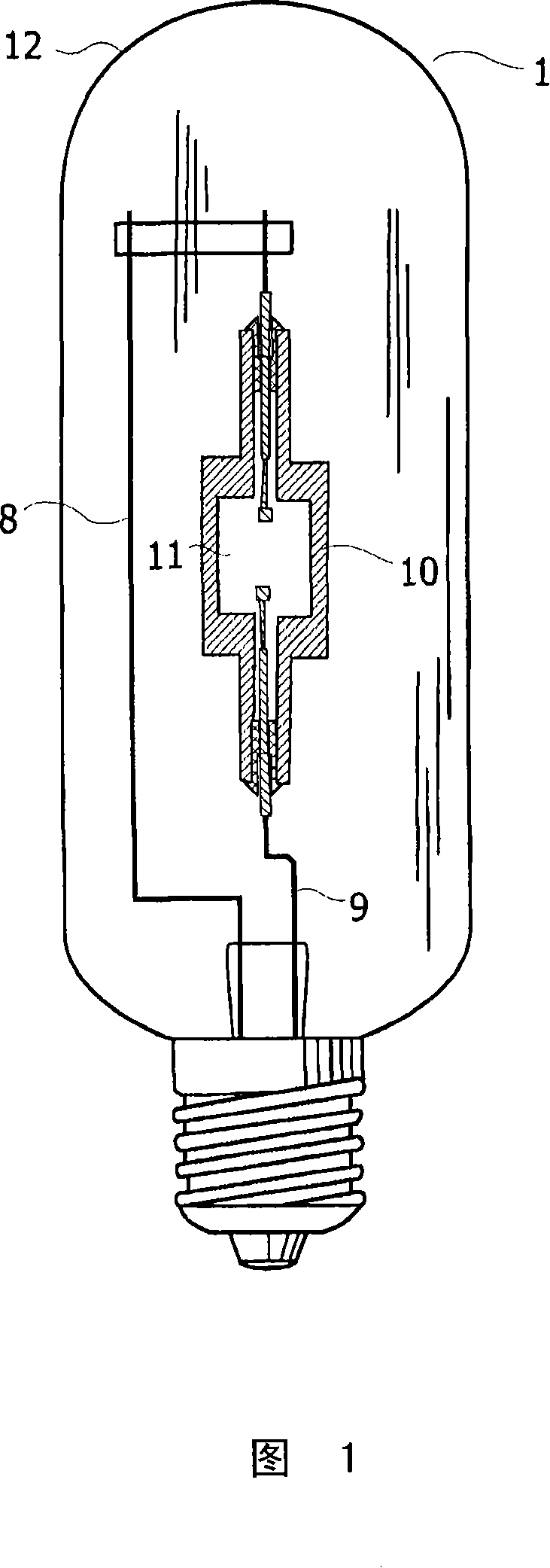
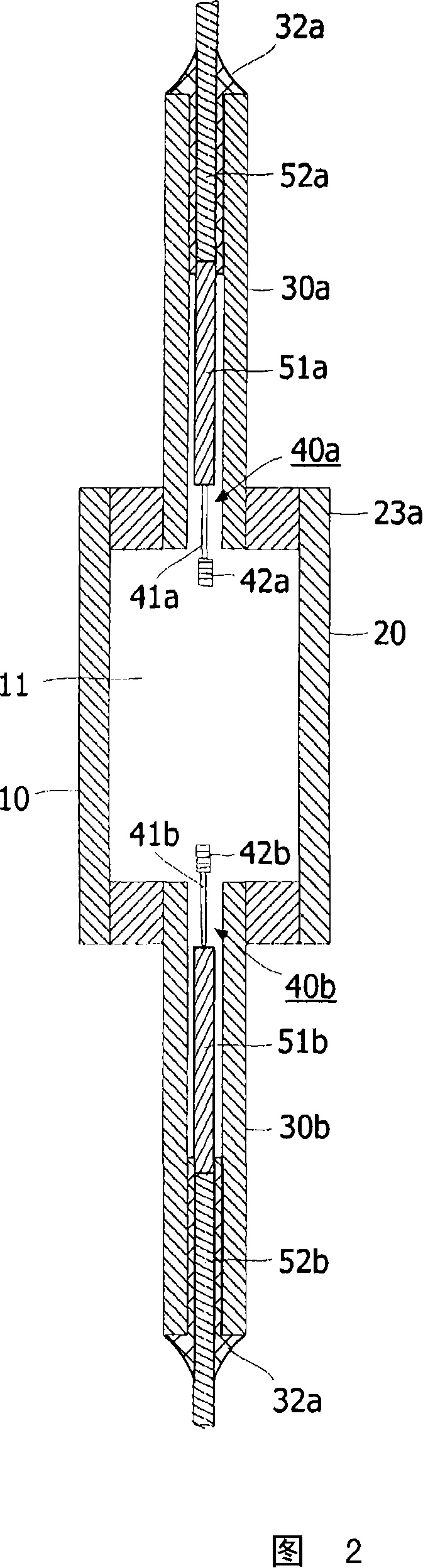
[0016] Fig. 1 shows a metal halide lamp 1, which comprises a discharge vessel 10, which is shown in cross-section and not to scale in Fig. 2, and which has a closed discharge space 11 The ceramic wall, the discharge space 11 contains ionizable fillers, in addition to Hg, the fillers also include NaI, CaI 2 , CeI 3 And MgI 2 .

[0017] Figure 2 shows the discharge vessel in detail. The discharge vessel has a ceramic wall 20 which is provided with protruding ceramic plugs 30a, 30b at either end to accommodate the electrical lead-in wires to the electrodes 40a and 40b, respectively. Each lead-in line includes anti-halide parts 51a, 51b and parts 52a, 52b, for example, the parts 51a, 51b are made of Mo, and the parts 52a, 52b are connected in an air-tight manner through, for example, ceramic glaze connections 32a, 32b. To the plugs 30a, 30b. In this specification, anti-halide is understood to mean that there is no or substantially no corrosive damage caused by halides, and no halogen ...


PUM


Abstract

The invention relates to a metal halide lamp (1) with high luminous efficacy and high red reproduction. This is achieved by a lamp comprising a discharge vessel (10) with ceramic walls enclosing a discharge space (11) comprising two electrodes and an ionizable filling comprising at least about 20 mol % calcium halide and one or more halides selected from the group consisting of Tl and rare earths, wherein the ionizable filler comprises magnesium halide, manganese halide or a mixture thereof in a molar amount of at least about 5 mol% total halide, A total amount of halides of between 10 and 15 mol % is preferred.

Description

Technical field [0001] The present invention relates to a metal halide lamp. This halide lamp comprises a discharge vessel with a ceramic wall. The discharge vessel encloses a discharge space. The discharge space contains two electrodes and an ionizable filling comprising a halide. It contains at least about 20 mol% of calcium halide and one or more halides, and the halides are selected from the group consisting of Tl and rare earths. Background technique [0002] In interior and exterior lighting, arc discharge lamps are increasingly used to replace incandescent lamps. However, arc discharge lamps do not render red as satisfactorily as incandescent light sources. In order to increase the red radiation, calcium halide is usually added to the filling. One or more halides selected from the group consisting of Tl and rare earth are added as a green radiator to obtain a white light source and further improve the luminous efficacy. In this specification, rare earth metals are understo...

Claims


Application Information

Patent Timeline
IPC IPC(8): H01J61/82H01J61/12
CPCH01J61/827H01J61/125
Inventor V·费希尔O·G·斯塔帕斯J·J·F·G·休茨
Owner SIGNIFY HLDG BV
Why Eureka
Try Eureka