
Energy-saving method for electric dust removing system

A technology of electrostatic precipitator and electric field, applied in power supply technology, electrostatic separation and other directions, can solve problems such as inability to distribute power

Inactive Publication Date: 2008-04-30
HANGZHOU YITIAN ELECTRONICS INFORMATION TECHN
View PDF0 Cites 7 Cited by
  • Summary
  • Abstract
  • Description
  • Claims
  • Application Information

AI Technical Summary

Problems solved by technology

But its technical point lies in the use of proportional regulators, which increase or decrease the power between the electric fields in a certain proportion, and cannot perform effective power distribution.

Method used


Image

  • Energy-saving method for electric dust removing system
  • Energy-saving method for electric dust removing system
  • Energy-saving method for electric dust removing system

Examples


Embodiment Construction

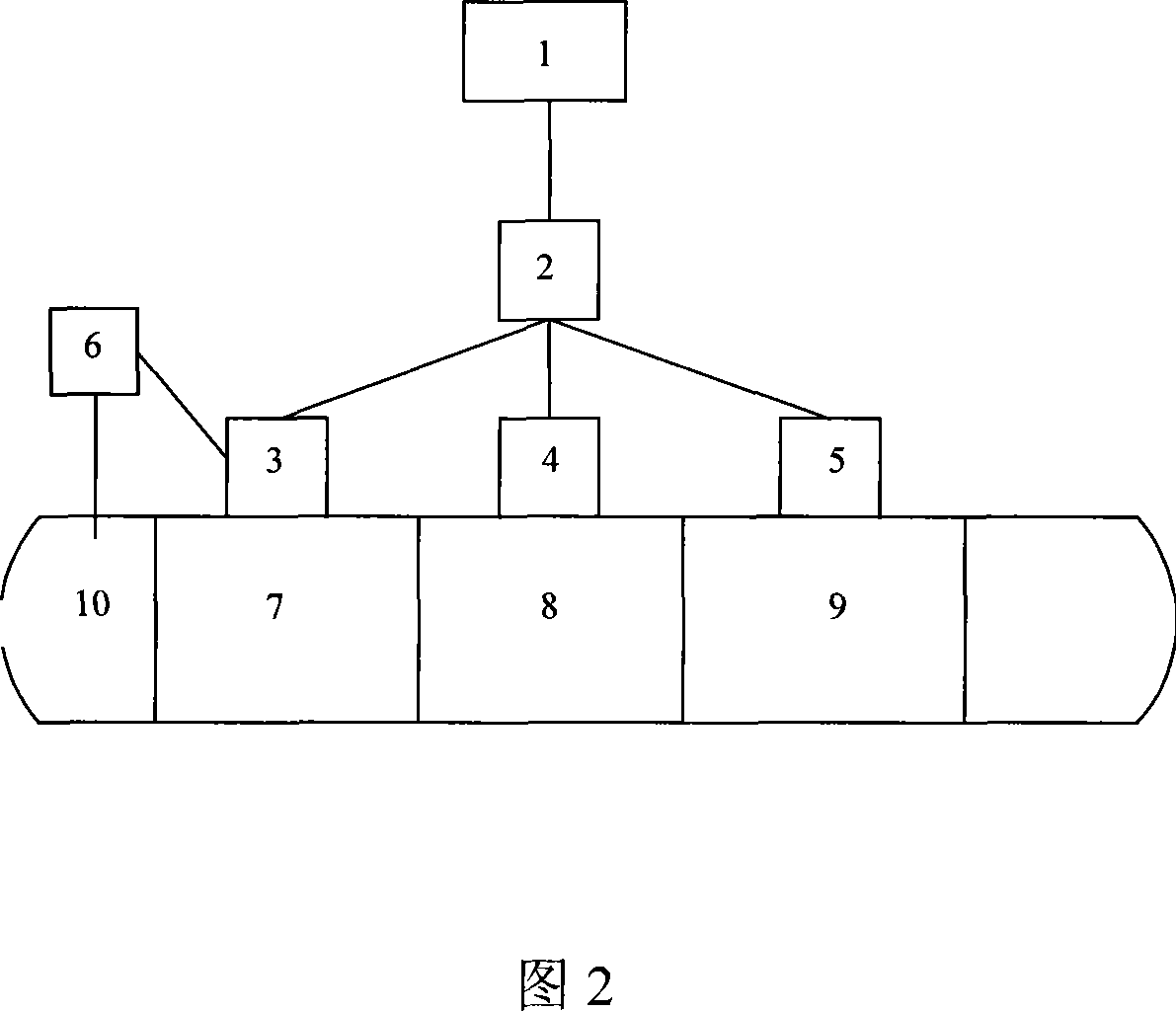
[0031] Figure 2 shows an electrostatic precipitator system, which has 3 electric fields, namely electric field I7, electric field II8 and electric field III9. The dust passes through the electric field I7, the electric field II8 and the electric field III9 and is discharged into the chimney 10, and a turbidity meter 6 is provided at the outlet of the chimney 10.

[0032] The electric field I7 is controlled by the controller I3, the electric field II8 is controlled by the controller II4, and the electric field III9 is ​​controlled by the controller III5. One end of the switch 2 is connected to the host computer 1, and the other end of the switch 2 is respectively connected to the controller I3 and the controller. II4 is connected to controller III5. That is, the controller I3, the controller II4 and the controller III5 are respectively connected to the upper computer 1 through the switch 2. The turbidity meter 6 is responsible for detecting the flue gas concentration, and it is con...


PUM


Abstract

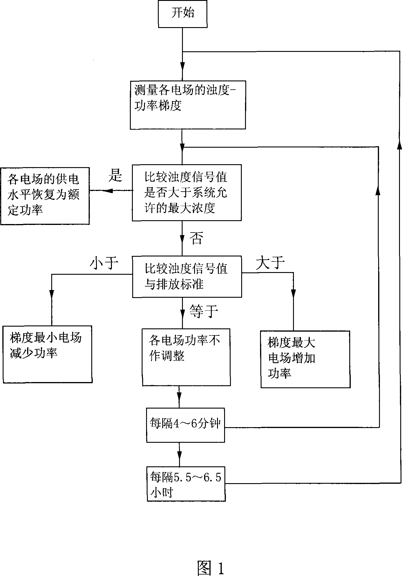
The invention discloses an energy-saving method for an electric dust removal system, comprising the following steps: 1) adjusting the power of one of the electric fields, and keeping the power of the remaining electric fields unchanged; 2) repeating the above step 1 for each of the remaining electric fields in sequence ); 3) Adjust the power of all electric fields to its original power; 4) When the turbidimeter signal is greater than the maximum concentration allowed by the system, adjust the power supply level of each electric field to its rated power; otherwise, enter step 5); 5) When the turbidity signal is less than the discharge standard, reduce the power of the gradient minimum electric field; when the turbidity signal is greater than the discharge standard, increase the power of the gradient maximum electric field, and when the turbidity signal is equal to the discharge standard, keep the power of all electric fields as its original power; 6) Repeat steps 4) to 5) above every 4 to 6 minutes. By using the method of the invention, the power distribution among the electric fields can be adaptively adjusted to realize maximum energy saving.

Description

Technical field [0001] The invention relates to a method for reducing energy consumption of an electric dust removal system. Background technique [0002] Electrostatic precipitator is a necessary accessory equipment for thermal power plants. Its function is to remove particulate smoke and dust in the flue gas emitted by burning stoves or oil-fired boilers, thereby greatly reducing the amount of smoke and dust discharged into the atmosphere; therefore, it is to improve the environment Important environmental protection equipment that pollutes and improves air quality. Its working principle is: when the flue gas passes through the flue in front of the main structure of the electrostatic precipitator, the flue gas is positively charged, and then the flue gas enters the electrostatic precipitator channel with multi-layer cathode plates; because the positively charged smoke and the cathode The mutual adsorption of the electric plates makes the particles in the flue gas adsorb on the ...

Claims


Application Information

Patent Timeline
Patent Type & Authority Applications(China)
IPC IPC(8): B03C3/66
Inventor 季军楼祖平郑春水韦魏
Owner HANGZHOU YITIAN ELECTRONICS INFORMATION TECHN
Learn More