Drilling machine

A drilling machine and workbench technology, which is applied to the parts of boring machine/drilling machine, portable drilling machine, drilling/drilling equipment, etc., can solve the problems of non-adjustable and difficult-to-process workpieces, and achieve large working space, good rigidity, and structure novel effects

Inactive Publication Date: 2008-04-30
POSITEC POWER TOOLS (SUZHOU) CO LTD
View PDF0 Cites 9 Cited by
  • Summary
  • Abstract
  • Description
  • Claims
  • Application Information

AI Technical Summary

Problems solved by technology

Generally, it can only meet the needs of drilling workpieces with different heights on the workbench, but cannot be adjusted in the horizontal direction, and it is difficult to process workpieces with large horizontal dimensions.

Method used


Image

  • Drilling machine
  • Drilling machine
  • Drilling machine

Examples


Embodiment Construction

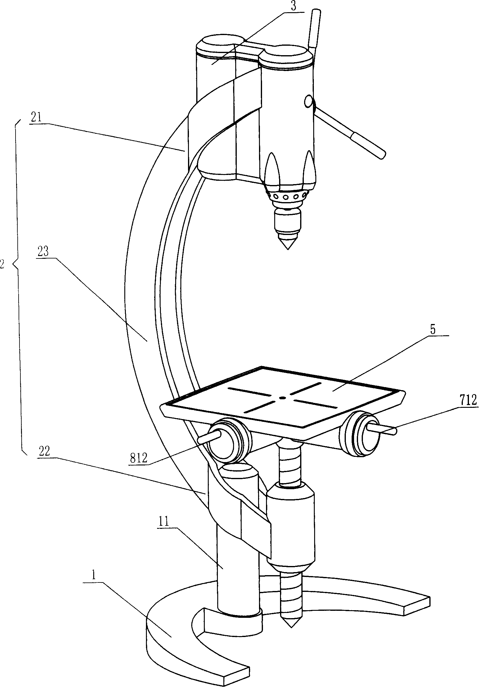
[0029] Such as figure 1 As shown, a drilling machine includes a base 1 , a bracket 2 matched with the base 1 , a headstock 3 matched with the bracket 2 , and a workbench 5 roughly arranged in the middle of the bracket 2 in the vertical direction. Wherein the base 1 is a "C"-shaped structure, and of course it can also be in other shapes; the bracket 2 includes a first end 21 matched with the headstock 3, a second end 22 matched with the column 11 of the base 1, and a first end 22 connected to the first The connection portion 23 between the end 21 and the first end 22. The connecting portion 23 is a traditional straight column, but a non-linear special-shaped structure. In this embodiment, the connecting portion 23 is a “C”-shaped structure.

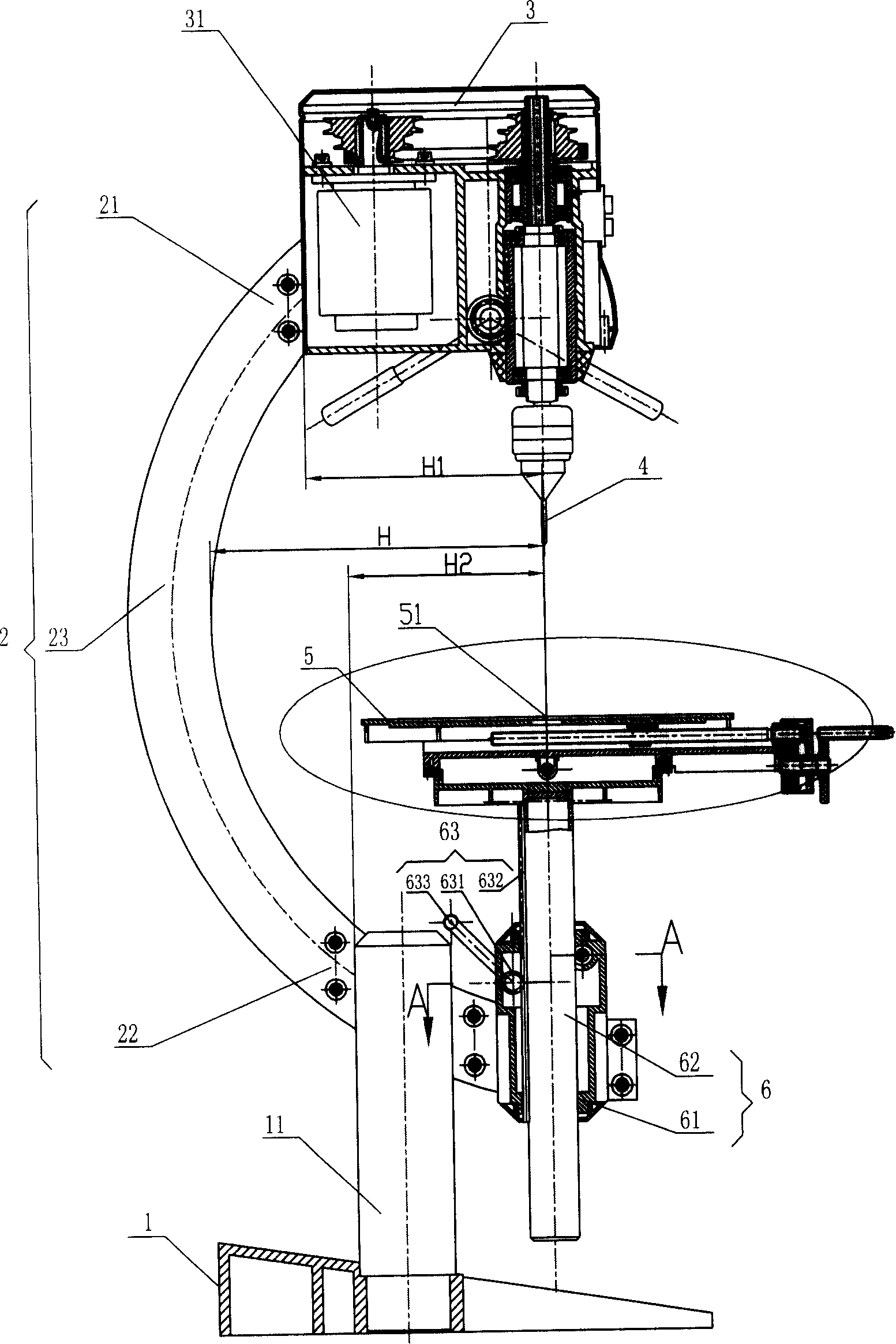
[0030] Such as figure 2 As shown, the horizontal distance H from any point of the connecting portion 23 to the vertical centerline 51 of the workbench 5 is greater than the horizontal distances H1 and H2 from any point of the first end ...


PUM


Abstract

A drill machine comprises a chassis (1), a support frame (2) adapted with the chassis (1), a main-shaft case (3) adapted with the support frame (2), and a working platform (5) which is approximately arranged in the middle of the support frame (2), wherein the support frame (2) is designed into a C shape to ensure the drill machine to have larger working space, and the chassis (1) and the support frame (2) are both designed into the C shape, ensuring relative novel formation and good rigidity. A sliding structure is arranged along the vertical direction, and the space is large, further a moving mechanism is arranged along the transverse direction, thereby the working platform is capable of being adjusted both along the vertical and transverse directions, and scale marks are also arranged on a hand wheel, thereby the accurate location can be realized in the time of operation with a plurality of holes.

Description

technical field [0001] The invention relates to a drilling machine, especially a drilling machine with a larger working space. Background technique [0002] There are mainly two integral forms of the traditional drilling machine, the cast box column or the round steel tube column. The former is more common in large drilling machines, and the latter is more common in small vertical drills or bench drills, radial drills, etc. These two types of drilling machines are mostly vertical columns because the columns are mostly vertical columns, and the workbench is slidably arranged on the columns. This structure makes the working space narrow and the shape is also relatively old. Generally, it can only meet the needs of punching workpieces with different heights on the workbench, but cannot be adjusted in the horizontal direction, and it is difficult to process workpieces with large horizontal dimensions. Contents of the invention [0003] In order to overcome the deficiencies o...

Claims


Application Information

Patent Timeline
IPC IPC(8): B23B45/02B23B47/00B23Q1/01B23Q1/25
Inventor 保罗·安德罗
Owner POSITEC POWER TOOLS (SUZHOU) CO LTD
Why Eureka
Try Eureka