Vacuum pipe butting structure

A technology of vacuum pipes and vacuum chambers, which is applied in the direction of pipes/pipe joints/fittings, flange connections, sleeve/socket connections, etc. It can solve the problems of cumbersome and complicated pipe butt joints, and achieve simple butt joints without welding and vacuuming easy effect

Inactive Publication Date: 2008-04-30
ZHANGJIAGANG FURUI SPECIAL EQUIP CO LTD
View PDF0 Cites 10 Cited by
  • Summary
  • Abstract
  • Description
  • Claims
  • Application Information

AI Technical Summary

Problems solved by technology

In this way, because the butt joint of the vacuum pipeline requires the use of welding equipment and vacuum equipment for on-site operations, the butt joint of the pipeline becomes extremely complicated and cumbersome

Method used


Image

  • Vacuum pipe butting structure
  • Vacuum pipe butting structure

Examples


Embodiment Construction

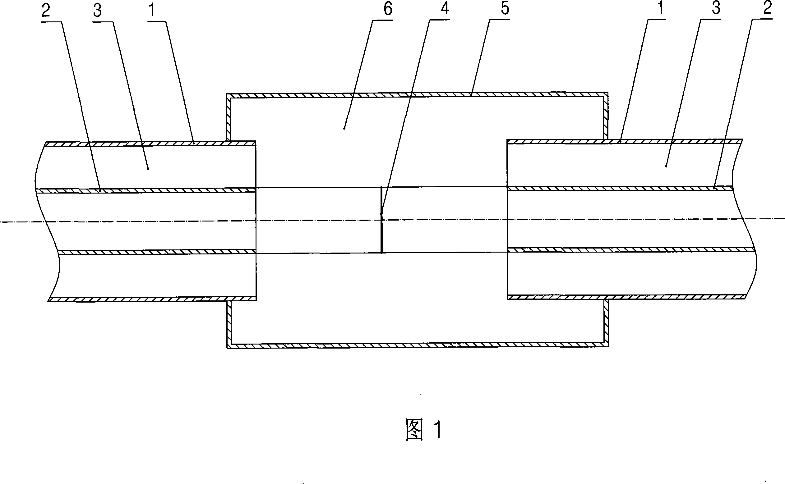
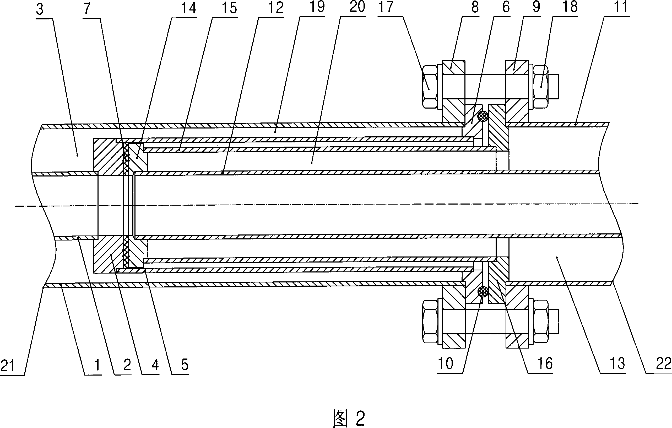
[0012] Specific embodiments of the present invention will be described in detail below in conjunction with the accompanying drawings.

[0013] As shown in Fig. 2, the butt joint structure of the vacuum pipeline according to the present invention includes: a pair of vacuum pipelines 21 and 22, the vacuum pipeline 21 includes an outer jacket 1 and an inner pipe 2, and a heat insulation is provided between the outer jacket 1 and the inner pipe 2. The vacuum chamber 3 and the vacuum pipeline 22 include an outer jacket 11 and an inner tube 12. A heat-insulating vacuum chamber 13 is arranged between the outer jacket 11 and the inner tube 12. A socket is arranged on the butt end of the inner tube 2 in the vacuum pipeline 21. The socket and the outer jacket 2 is provided with a socket vacuum chamber 19 communicating with the heat-insulating vacuum chamber 3, and a plug that matches the socket is provided on the butt end of the inner tube 12 of the vacuum pipeline 22, and a spacer is pr...


PUM


Abstract

The invention discloses a vacuum pipeline butt joint structure which can make butt joint of vacuum pipelines to be exceedingly convenient. The butt joint structure comprises a pair of vacuum pipelines each of which contains an outer sleeve and an inner pipe with a thermal-insulation vacuum cavity between; the butt joint end of the inner pipe of one vacuum pipeline is provided with a socket; a socket vacuum cavity communicating with the thermal-insulation vacuum cavity in the vacuum pipeline is arranged between the socket and the outer sleeve; the butt joint end of the inner pipe of the other vacuum pipeline is provided with a plug matching with the socket; a plug vacuum cavity communicating with the thermal-insulation vacuum cavity in the vacuum pipeline is arranged between the plug and the outer sleeve; a seal ring is arranged between the top of the plug and the bottom of the socket; the pair of vacuum pipelines is fixed together via a pair of flanges on the outer sleeves of the pipelines. The invention is mainly used for butt joint of vacuum pipelines for transmitting low-temperature liquids such as liquid nitrogen, liquid argon, liquid oxygen, liquefied natural gas, etc.

Description

technical field [0001] The invention relates to a butt joint structure of a vacuum pipeline. Background technique [0002] As shown in Figure 1, the vacuum pipeline used to transmit cryogenic liquids such as liquid nitrogen, liquid argon, liquid oxygen, and liquefied natural gas (LNG) has a structure including: an outer jacket 1 and an inner pipe 2 that are set together, and the outer jacket 1 and the inner pipe 2 is provided with a thermal insulation vacuum chamber 3. When two vacuum pipelines are butted, it is necessary to weld the butt joint surfaces 4 of the inner tubes 2 of the two vacuum pipelines on site, and then weld the casing 5 and the outer jackets 1 of the two vacuum pipelines together, and the exposed inner The tube 2 covers and forms a protective cavity 6, and the protective cavity 6 is evacuated by vacuum equipment. In this way, since the butt joint of the vacuum pipeline requires the use of welding equipment and vacuum equipment for on-site operations, the...

Claims


Application Information

Patent Timeline
Patent Type & Authority Applications(China)
IPC IPC(8): F16L23/16F16L21/00
Inventor 袁卫峰
Owner ZHANGJIAGANG FURUI SPECIAL EQUIP CO LTD
Why Eureka
Try Eureka