Main bearing support for a large two-stroke diesel engine

A technology for diesel engines and engines, applied to engine components, engine frames, combustion engines, etc., can solve problems affecting bearing bushes, etc., and achieve the effect of reducing the amount of time and shortening the transmission time

Inactive Publication Date: 2008-04-30
曼能解决方案(曼能解决方案德国股份公司)分公司
View PDF0 Cites 6 Cited by
  • Summary
  • Abstract
  • Description
  • Claims
  • Application Information

AI Technical Summary

Problems solved by technology

However, the repaired part of the main bearing support (heat-affected zone, HAZ) will become even harder after heat treatment than the rest of

Method used


Image

  • Main bearing support for a large two-stroke diesel engine
  • Main bearing support for a large two-stroke diesel engine
  • Main bearing support for a large two-stroke diesel engine

Examples


Embodiment Construction

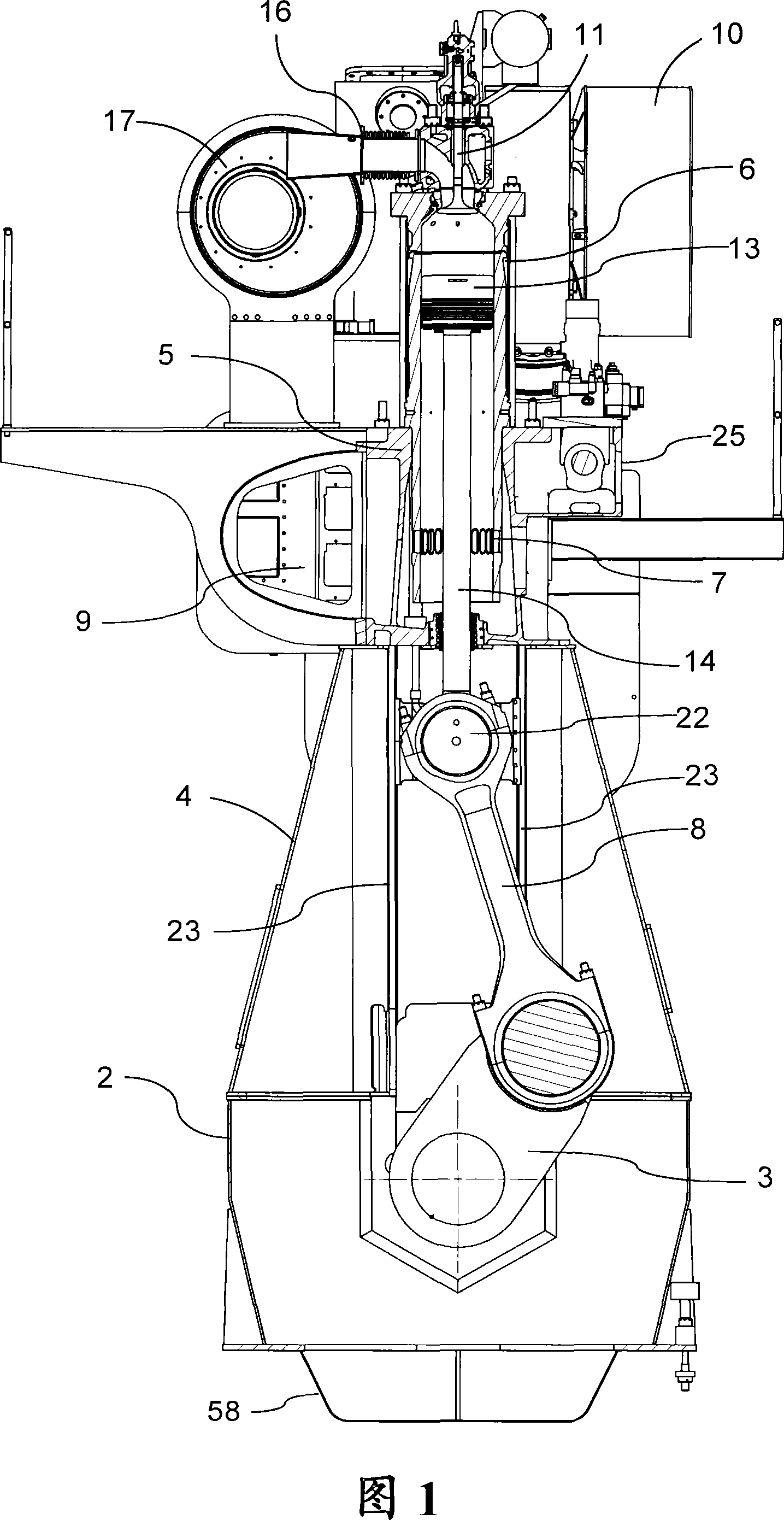
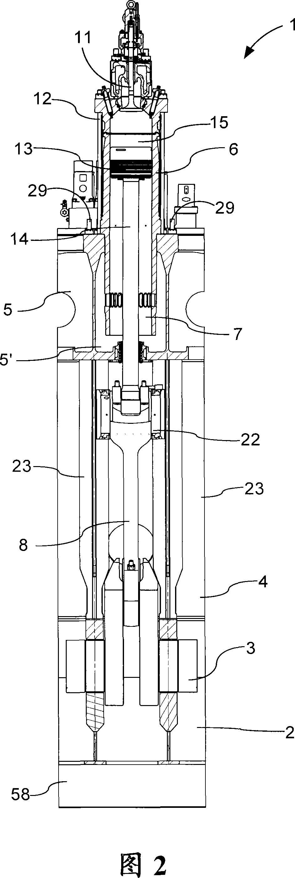
[0043] Figures 1 and 2 show respectively a cross-sectional view and a longitudinal sectional view (for one cylinder) of an engine 1 according to a preferred embodiment of the invention. The engine 1 is a crosshead single-flow low-speed two-stroke diesel engine, which can be a propulsion system in a ship or a prime mover in a power plant. These engines generally have 3 to 4 in-line cylinders. An engine 1 is built from a foundation 2 with main bearings for a crankshaft 3 .

[0044] Crankshaft 3 is a semi-combined type. The semi-combined type is made of forged or cast steel bellcranks connected to the main journal by a shrink fit connection.

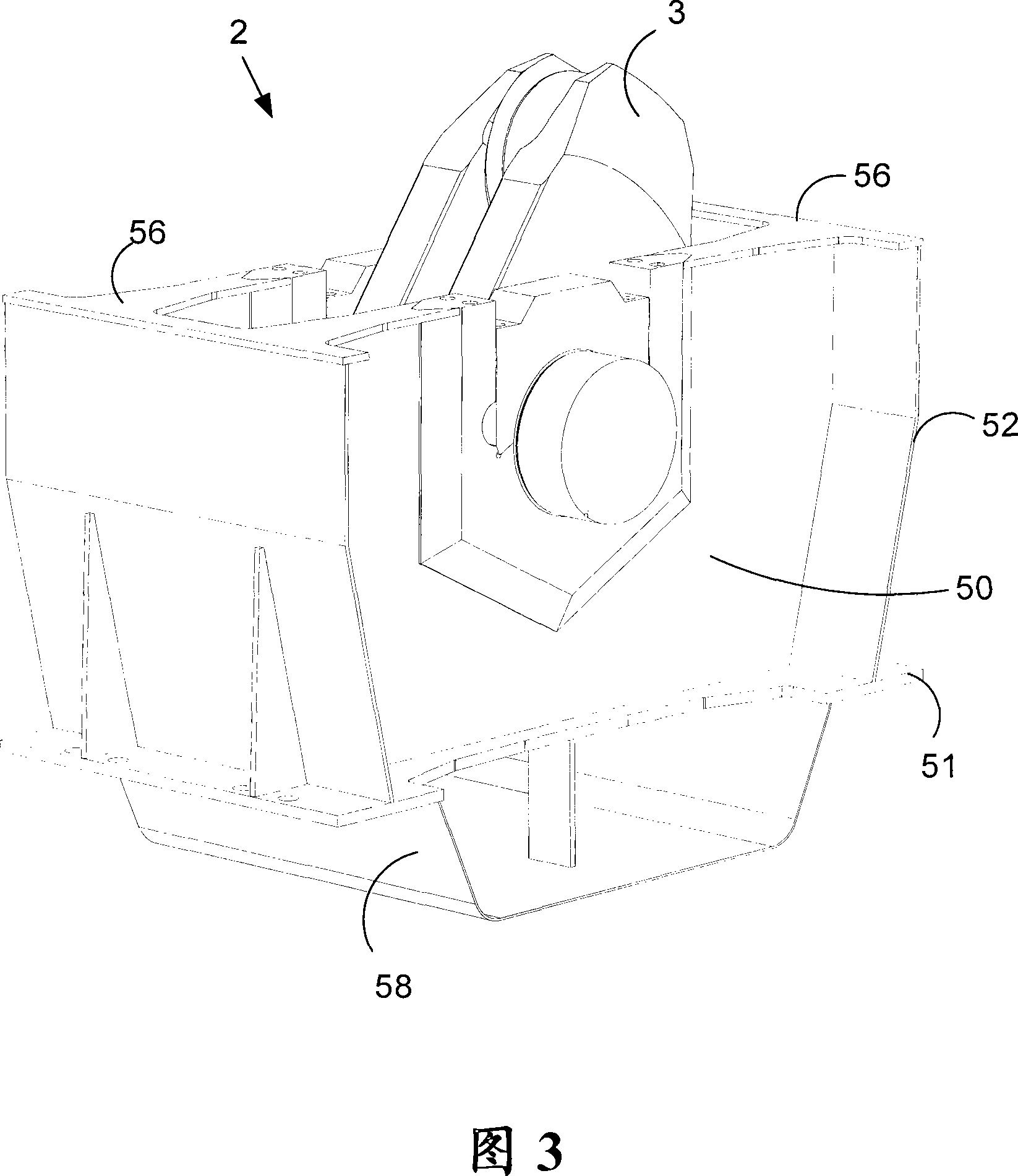
[0045] The base 2 can be made in one piece or divided into several parts of suitable size according to the manufacturing equipment. The base consists of side walls and beams welded to the bearing supports. Cross beams are also referred to as "transverse stringers" in the prior art. An oil pan 58 welded to the bottom of the base 2 colle...


PUM


Abstract

A large two-stroke diesel engine of the crosshead type with a bedplate, a frame box mounted on the bedplate and a cylinder frame mounted on the frame box. The bedplate comprises welded cross girders with the main bearings for the crankshaft. The cross girders include a main bearing support made from a rolled steel slab or plate with an arc shaped support surface machined therein. The slab or plate is welded to the webplates to form a cross girder.

Description

technical field [0001] The present invention relates to a main bearing support for a large two-stroke diesel engine of the crosshead type, and also to a method for manufacturing such a main bearing support. Background technique [0002] Large two-stroke diesel engines of the crosshead type, used for example as propellers in large ocean-going vessels or as prime movers in power plants, comprise three main housing parts. Seen from the bottom up, these parts are the so-called base, frame box and cylinder block. The three housing parts are held together by stay bolts. The main bearings for the crankshaft are located in the base. [0003] The base of the existing engine consists of high welded stringers and welded cross members with cast steel bearing supports, ie the base is of fully welded construction of rolled sheet metal except for the bearing supports. The beam consists of two webs between which the cast main bearing supports are welded. [0004] The main bearing suppor...

Claims


Application Information

Patent Timeline
IPC IPC(8): F02F7/00F16M1/025
CPCF16C5/00F02F7/0053F16C9/02F02B25/02
Inventor 弗莱明·伦德
Owner 曼能解决方案(曼能解决方案德国股份公司)分公司
Why Eureka
Try Eureka