Foldable light mass balance ambulation single wheel electric vehicle

A mass balance, electric vehicle technology, applied in electric vehicles, single-wheeled bicycles, bicycles, etc., can solve the problems of not giving full play to the advantages of light electric vehicles, inconvenience to carry, heavy weight, etc., and achieve light weight, convenient movement, and light weight. Effect

Inactive Publication Date: 2008-05-07
HARBIN INST OF TECH
View PDF0 Cites 19 Cited by
  • Summary
  • Abstract
  • Description
  • Claims
  • Application Information

AI Technical Summary

Problems solved by technology

[0003] The purpose of the present invention is to provide a foldable light-mass balanced walking single-wheel electric vehicle, which can solve the existing problems of large volume, heavy weight, inconvenient portability, and failure to give full play to the advantages of light electric vehicles in existing light electric vehicles

Method used


Image

  • Foldable light mass balance ambulation single wheel electric vehicle
  • Foldable light mass balance ambulation single wheel electric vehicle
  • Foldable light mass balance ambulation single wheel electric vehicle

Examples


specific Embodiment approach 1

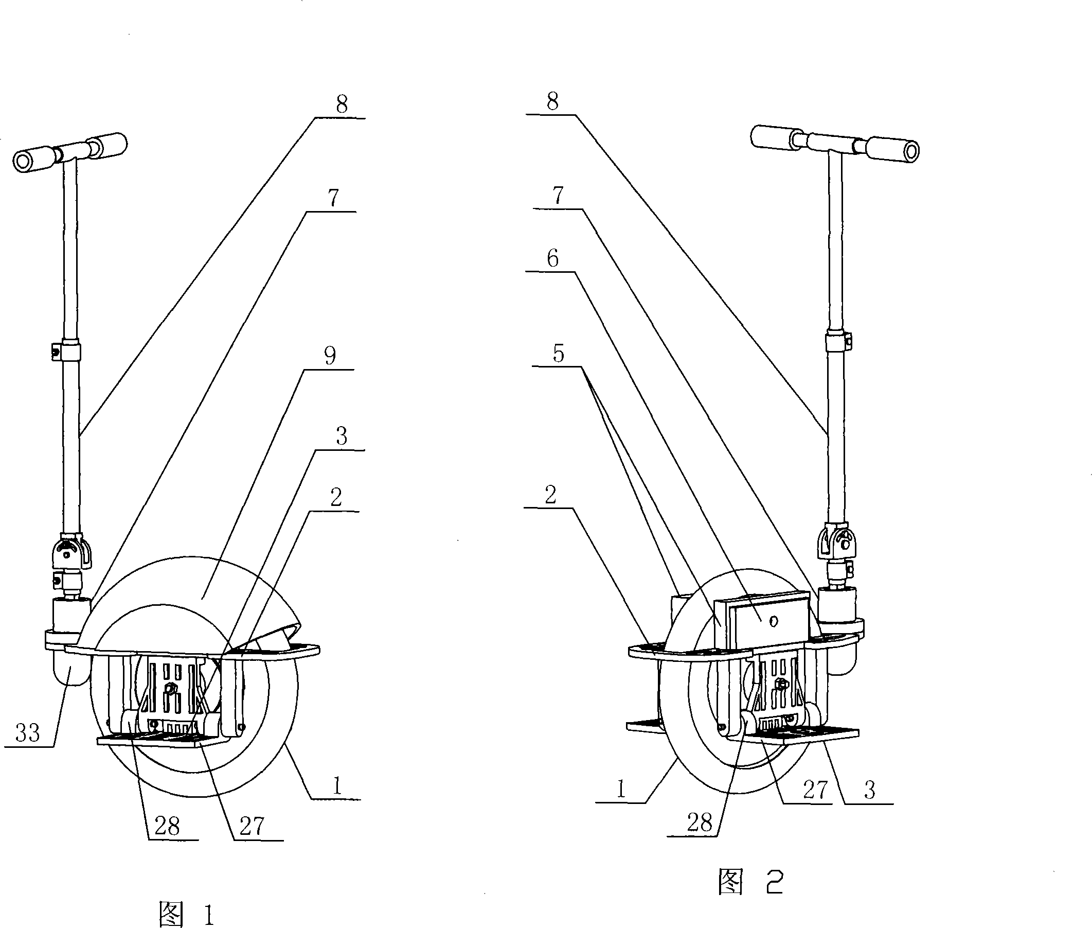
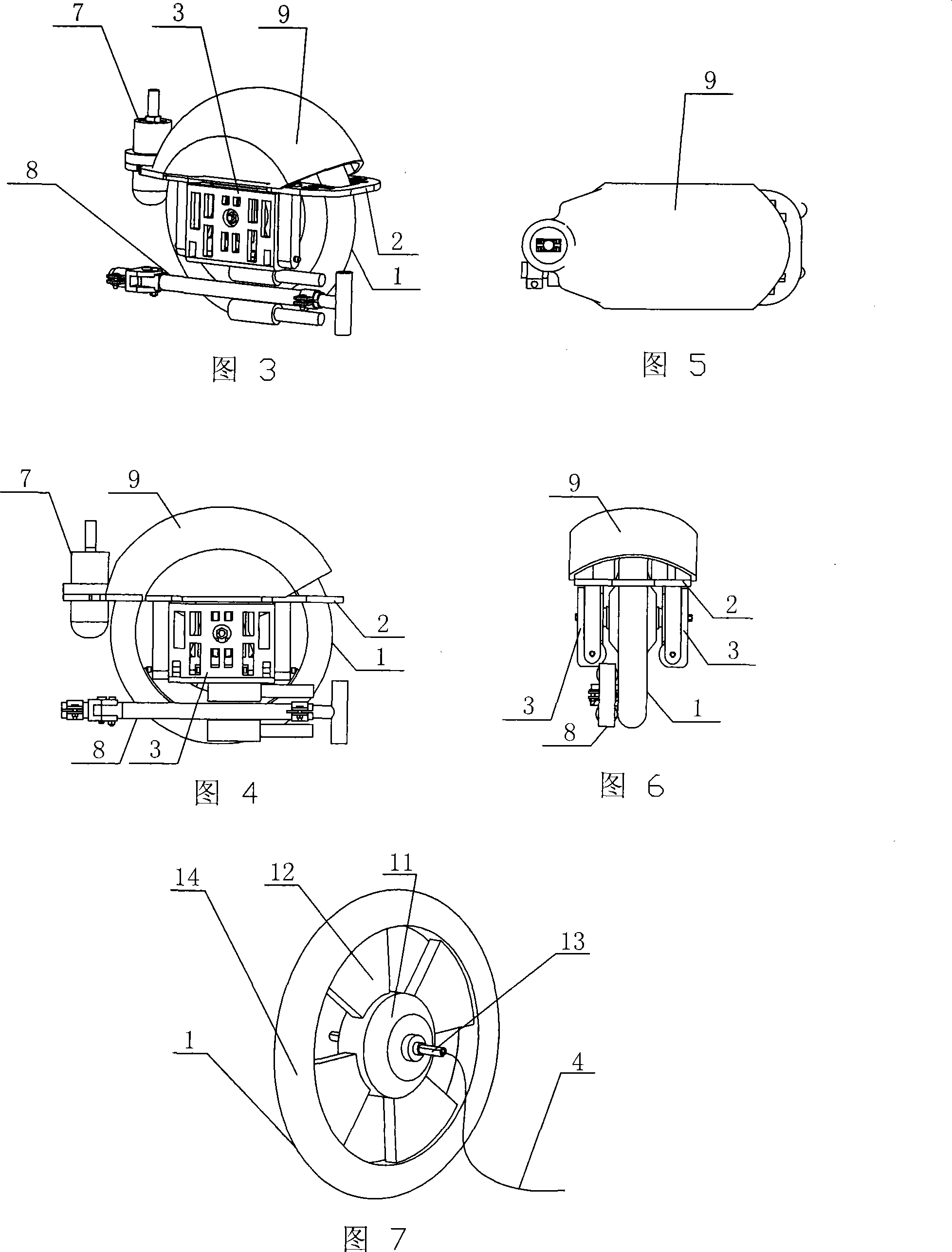
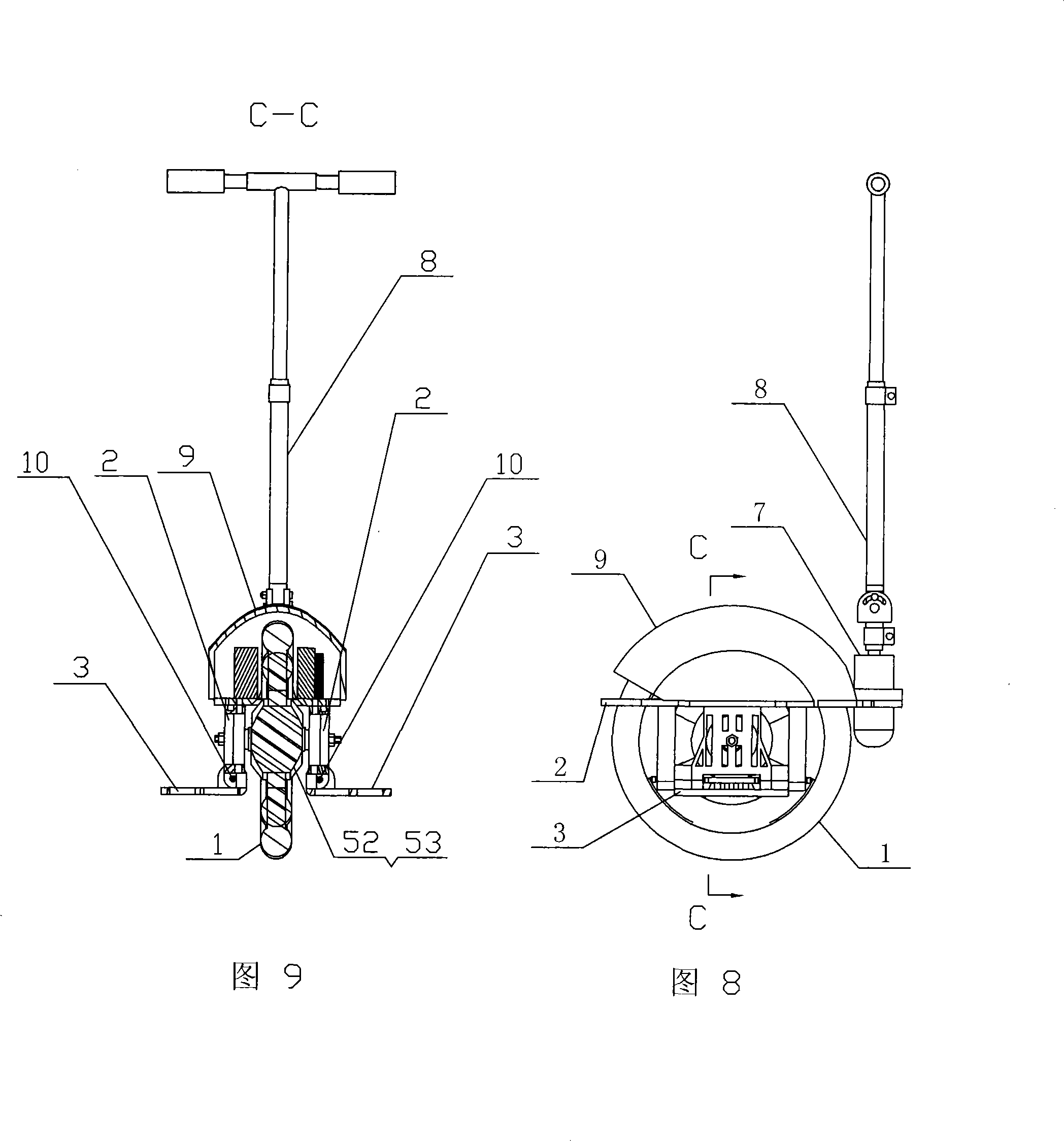
[0007] Specific embodiment one: this embodiment is described in conjunction with Fig. 1~Fig. Circuit board 6, sensor 7, handrail 8, upper cover 9, connecting shaft 10 are composed; described motor 52 and speed reducer 53 are all fixedly installed in the wheel hub 11 of walking wheel 1, the output end of motor 52 and the input of speed reducer 53 end transmission connection, the output end of the reducer 53 is fixedly connected to the spoke plate or spoke 12 of the road wheel 1, the vehicle body platform 2 is set on the road wheel 1 and fixedly connected to the motor shaft 13, the two wheels of the road wheel 1 The cavity between the side and the vehicle body platform 2 is equipped with a battery 5 and a circuit board 6 affixed to the vehicle body platform 2, and the power input end of the motor 52 is connected to the circuit through the electrical connection 4 drawn from the hollow hole of the motor shaft 13. The power output end of the board 6 is connected, the power input en...

specific Embodiment approach 2

[0008] Specific embodiment two: present embodiment is described in conjunction with Fig. 7, and the walking wheel 1 of present embodiment is made up of wheel hub 11, spoke plate or spoke 12, rim 14; The spoke plate or the spokes 12 uniformly distributed along the circumference of the wheel rim 14 are fixedly installed between the wheel rim 14 and the wheel rim 14, and the walking wheel 1 can adopt an integral structure or a split structure. Set up in this way, the structure is simple, the use is safe and reliable, and the travel wheel 1 is driven to rotate by the speed reducer 53 . The road wheel 1 can also be purchased from outside, and the manufacturer integrates the motor 52 and the speed reducer 53 in the wheel hub 11 of the road wheel 1 . Other components and connections are the same as those in the first embodiment.

specific Embodiment approach 3

[0009] Specific Embodiment Three: This embodiment is described in conjunction with FIGS. 10 to 12. The handrail 8 of this embodiment is composed of a handhold rod 15, a "T"-shaped rod 16, a connecting rod 17, a connecting member 18, a connecting shaft 19, and a locking The pin 100 and the clamp 20 are composed; the holding bar 15 is composed of a metal intubation 21 and a soft sleeve 22, and the connecting member 18 is composed of a connecting socket 23 and a connecting sleeve 24, and the bottom of the connecting socket 23 The end face is affixed to the upper end face of the connecting socket 24, and the two ends of the horizontal bar 25 of the "T"-shaped bar 16 are respectively plugged with one end of the metal cannula 21, and the other end of the metal cannula 21 is connected with the soft One end of the sleeve 22 is plugged in, and the lower end of the "T" shaped rod 16 is installed in the inner hole of the upper end of the connecting rod 17. The lower end of the connecting ...


PUM


Abstract

The invention discloses a foldable light mass balancing walking monowheel electric vehicle, and relates to a monowheel electric vehicle. The invention aims at solving the problems existing in the prior light type electric vehicle that the volume is large, the mass is heavy, the carrying is inconvenient, and the advantages of the light type electric vehicle cannot be fully exerted. A motor (52) and a speed reducer (53) are fixedly installed in a wheel hub (11) of a traveling wheel (1), the motor (52) is connected with the speed reducer (53), the speed reducer (53) is fixed and connected with the web or the spoke (12) of the traveling wheel (1), a vehicle body platform (2) is sleeved on the traveling wheel (1) and is fixed and connected with a motor shaft (13), a battery (5) and an electric circuit board (6) are installed between the traveling wheel (1) and the vehicle body platform (2), the motor (52) is connected with the electric circuit board (6) through an electric connecting wire (4), the electric circuit board (6) is connected with the battery (5), an upper cover (9) is rightly arranged above the traveling wheel (1) and is fixed and connected with the vehicle body platform (2), a pedal plate (3) movably connected with the vehicle body platform (2) is respectively arranged on the both sides of the traveling wheel (1) through a connecting shaft (10), and an arm rest (8) is connected with a sensor (7). The invention has the advantages that the invention can be folded, the volume is small, the weight is light, the moving is convenient, and the carrying is convenient.

Description

technical field [0001] The invention relates to a single-wheel electric vehicle. Background technique [0002] Transportation methods such as automobiles, motorcycles, and electric bicycles powered by electric energy will become important ground transportation tools for human beings in the future. According to the definition commonly used at home and abroad, light electric vehicles refer to low-speed electric vehicles with small and medium power such as electric bicycles and electric scooters. At present, the technology of light electric vehicles such as four-wheel electric vehicles, two-wheel electric motorcycles, parallel two-wheel electric scooters, and electric bicycles at home and abroad is relatively mature, and there are many formed products in the market. But these electric vehicles have a common shortcoming, namely bulky, heavy, not easy to carry. Especially limited by the current development of battery technology, the market positioning is not accurate enough, an...

Claims


Application Information

Patent Timeline
Patent Type & Authority Applications(China)
IPC IPC(8): B62K17/00B62K11/00B60K1/00
CPCB60L15/20B60L2200/14B60L2220/44B60L2240/12B60L2240/26B60L2240/421B60L2240/423B60L2260/34Y02T10/72B60L50/66Y02T10/64Y02T10/70B62K1/00B62K11/007
Inventor 刘伊威
Owner HARBIN INST OF TECH
Why Eureka
Try Eureka