Integral heat pump of heat pump laundry dryer

A technology of a washing-drying machine and a heat pump device, applied in the field of washing machines, can solve problems such as troublesome maintenance, and achieve the effect of easy installation and maintenance

Active Publication Date: 2008-05-07
QINGDAO HAIER DRUM WASHING MACHINE
View PDF0 Cites 10 Cited by
  • Summary
  • Abstract
  • Description
  • Claims
  • Application Information

AI Technical Summary

Problems solved by technology

However, once the refrigeration cycle system of this kind of heat pump washing machine breaks down, the maintenance is quite troublesome.

Method used


Image

  • Integral heat pump of heat pump laundry dryer
  • Integral heat pump of heat pump laundry dryer
  • Integral heat pump of heat pump laundry dryer

Examples


Embodiment 1

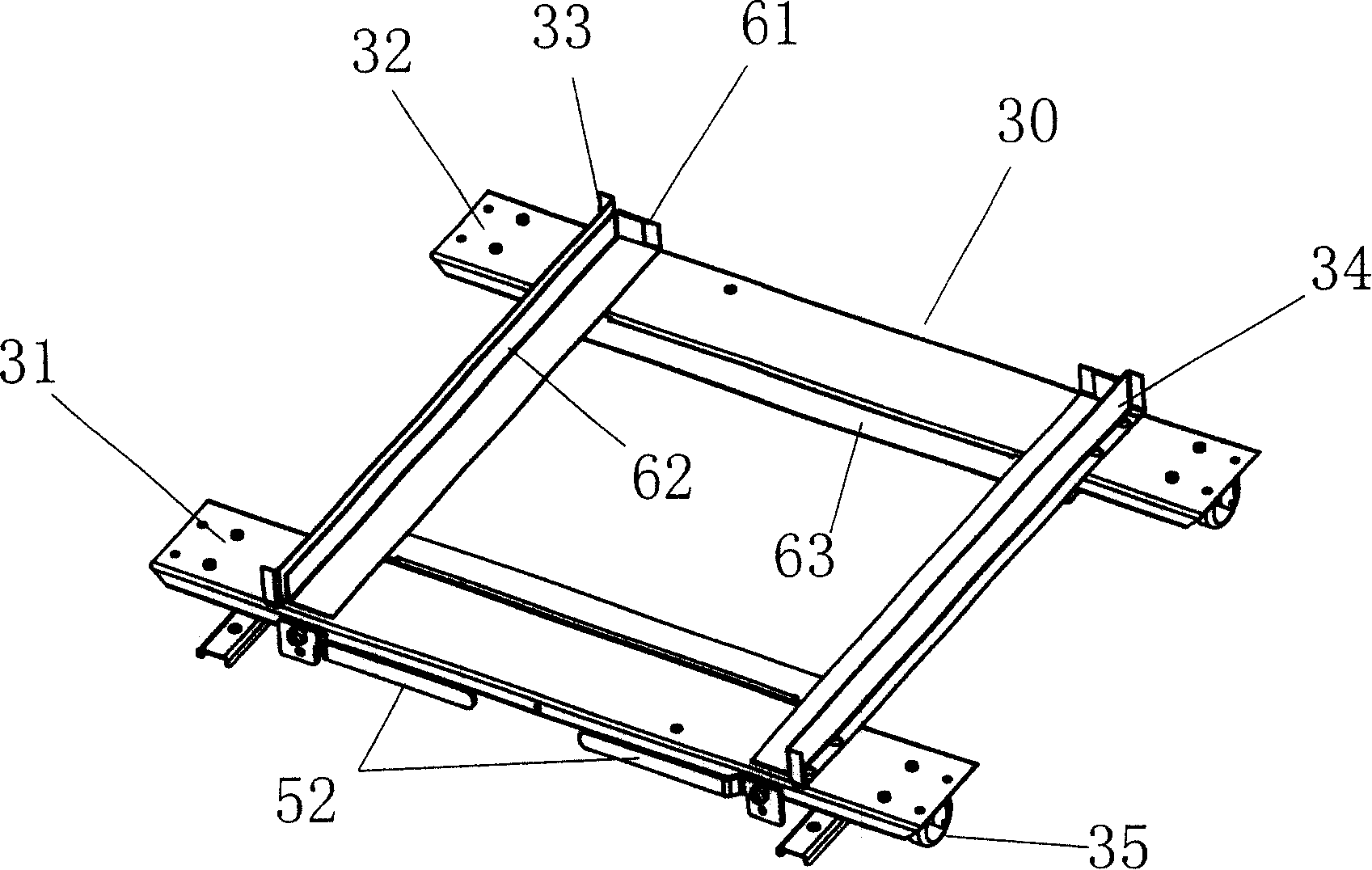
[0034] image 3 , Figure 4Shown is a specific embodiment of a conveying device with a lifting mechanism. The lifting device described in this embodiment is a lifting device realized by using a cam. Specifically, the left and right ends of the front and rear cross bars of the bottom frame 30 pass Provide a rotating shaft 51 with two identical cams 50, the cams on the left and right rotating shafts 51 are arranged oppositely, and the end of the rotating shaft is provided with a handle 52. On the four cams 50 of the above-mentioned two rotating shafts, a fixing hole 53 is provided on the handle.

[0035] The positioning device is a rectangular frame with rectangular box positioning baffles 61, 62 for the cooling and heat pump box. Both sides of the rectangular frame are provided with slideways for pushing and pulling out the cooling and heat pump box. The rectangular frame A slide block or a slide plate 63 (the specific embodiment shown in the figure is a slide plate) is provi...

Embodiment 2

[0039] Embodiment 2 is a four-cam lifting device that can realize the steady lifting of the entire refrigeration heat pump box by pulling the handle 52 at the end of a rotating shaft with one hand. Rod mechanism to realize four-cam synchronous rotation lifting. Specifically, the lifting mechanism is to pass a rotating shaft provided with two identical cams 50' on the left and right ends of the front and rear cross bars 31, 32 of the bottom frame 30, and the cams 50' on the left and right rotating shafts are arranged in the same direction, wherein A handle 52' is provided at one end of the rotating shaft, and a crank 53 is provided at the end of the other rotating shaft, and a connecting rod 54 is connected between the crank 53 and the handle 52' to form a parallelogram; the refrigeration heat pump box 1 The rectangular box body is arranged on the four cams of the two rotating shafts through a positioning device 60, and a fixing hole 63 is provided on the handle.

[0040] When...

Embodiment 3

[0043] The lifting mechanism can also use a jack, specifically, jacks are provided at the four corners of the bottom frame, and the rectangular box body of the refrigeration heat pump box is set on the jack through a positioning device, and the positioning device Long holes are provided, and fastening screws for locking the positioning device through the long holes of the positioning device are arranged on the bottom frame.

[0044] Described jack is hydraulic jack or screw jack. When the screw jack is used, the synchronous rotation of the two rotating shafts can be realized through a bevel gear transmission mechanism or a sprocket transmission mechanism.

[0045] The positioning device in each of the above embodiments may also be a slider or a slide plate provided at the bottom of the rectangular box body of the heat pump box and matched with the inner side of the rectangular bottom frame. When the rectangular box is raised, the horizontal movement does not occur through the...


PUM


Abstract

An integral heat pump device for a heat pump washer-dryer. The washer-dryer includes: an outer shell, an inner tub, and an outer tub. A hot air inlet is provided at the rear of the outer tub of the washer-dryer. A hot air outlet is provided, and the heat pump device is provided at the bottom of the washer-dryer. The bottom of the box body is provided with a conveying device, and a lifting mechanism for lifting the heat pump box is provided on the conveying device. The heat pump box equipped with the heat pump is pushed into the washing machine as a whole through the conveying device, and the heat pump box on the heat pump box is pushed into the washing machine through the lifting mechanism. The air inlet and the air outlet are sleeved on the hot air outlet and the hot air inlet of the outer tub of the washing and drying machine. The integral heat pump device of the heat pump washing and drying machine of the present invention can push and pull out the entire refrigeration heat pump box, which is convenient for installation and maintenance.

Description

technical field [0001] The present invention relates to a washing machine, and in particular, the present invention relates to an integrated heat pump device for a heat pump washer-dryer that facilitates maintenance of the heat pump system. Background technique [0002] In another patent application of the applicant, a technical scheme of a heat pump washing machine is proposed, the structure of which is as follows: figure 1 As shown, it includes a shell, in which an outer tub 21 is arranged, and a rotatable inner tub 20 is arranged inside the outer tub 21, and some holes are arranged on the side of the inner tub 20 to facilitate the circulation of washing liquid and air, wherein the The rear side of the outer barrel 21 of the washing machine is provided with a hot air inlet 23, and the front end of the outer barrel 21 of the drum is provided with a hot air outlet 17. An air duct is connected to the hot air inlet 23 at the hot air outlet 17, and an evaporator 8 is placed in ...

Claims


Application Information

Patent Timeline
Patent Type & Authority Applications(China)
IPC IPC(8): D06F39/04F24H4/06
Inventor 吕佩师席磊黄本财徐永洪
Owner QINGDAO HAIER DRUM WASHING MACHINE
Why Eureka
Try Eureka