Method and device for detecting tooth matching angle of gear

An angle detection and gear technology, which is applied in gear tooth manufacturing devices, measuring devices, machine gear/transmission mechanism testing, etc., can solve the problems of inoperable gear 2 high-speed rotation, difficult tooth detection, signal interval limitation, etc.

Active Publication Date: 2008-05-07
MITSUBISHI HEAVY IND MACHINE TOOL CO LTD
View PDF2 Cites 30 Cited by
  • Summary
  • Abstract
  • Description
  • Claims
  • Application Information

AI Technical Summary

Problems solved by technology

[0012] In contrast, in contact sensors such as contact probes, detection takes time, so it is difficult to detect all teeth in a short time and obtain the meshing angle with high precision.
In addition, when using a proximity sensor, it is difficult to meet the above requirements because it takes time to obtain the meshing angle for the following reasons
[0013] (1) Due to the slow response speed of the proximity sensor, the working gear 2 cannot be rotated at high speed
Ther

Method used


Image

  • Method and device for detecting tooth matching angle of gear
  • Method and device for detecting tooth matching angle of gear
  • Method and device for detecting tooth matching angle of gear

Examples


Embodiment Construction

[0073] Embodiments of the present invention will be described in detail below with reference to the accompanying drawings.

[0074] (structure)

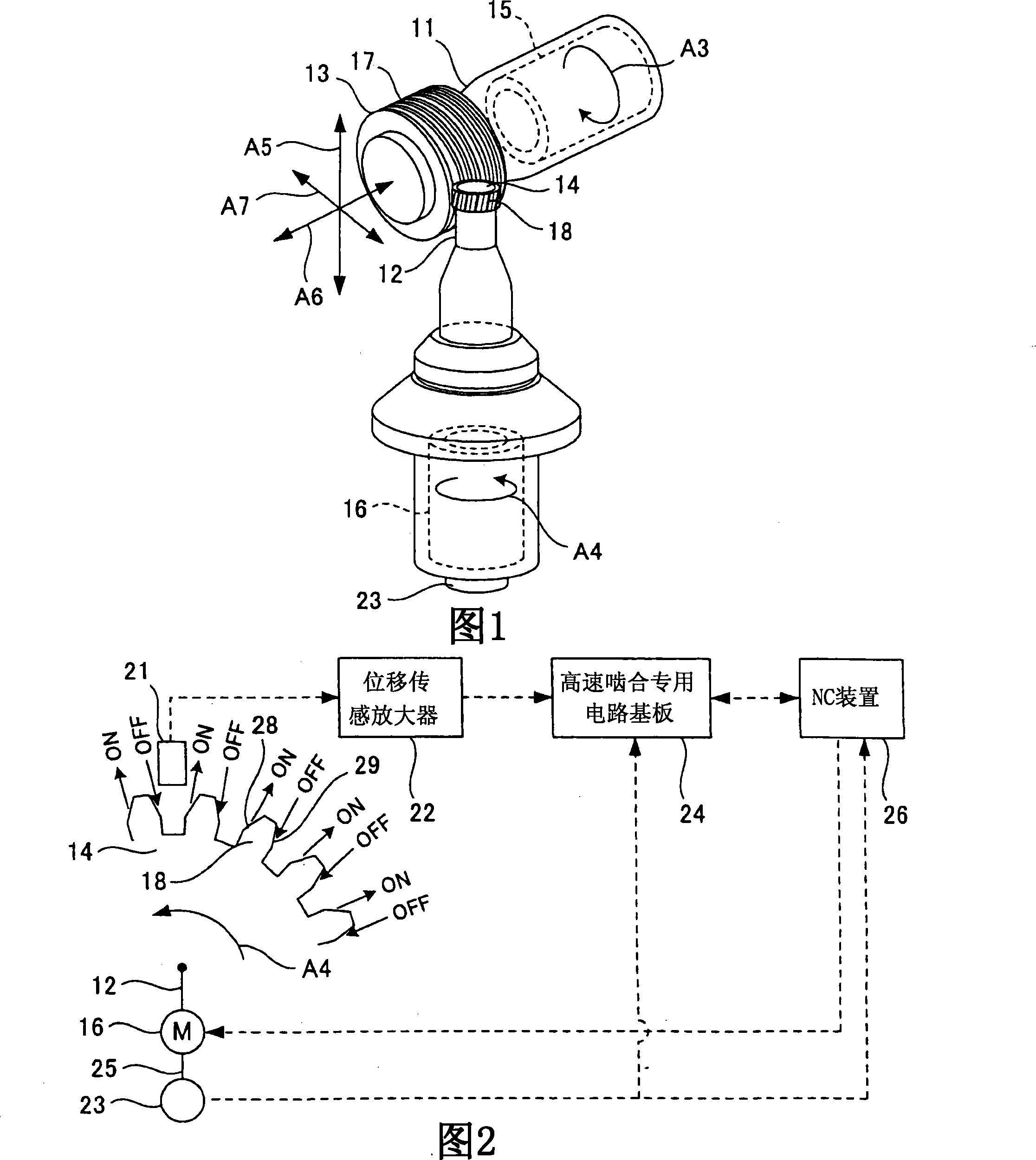
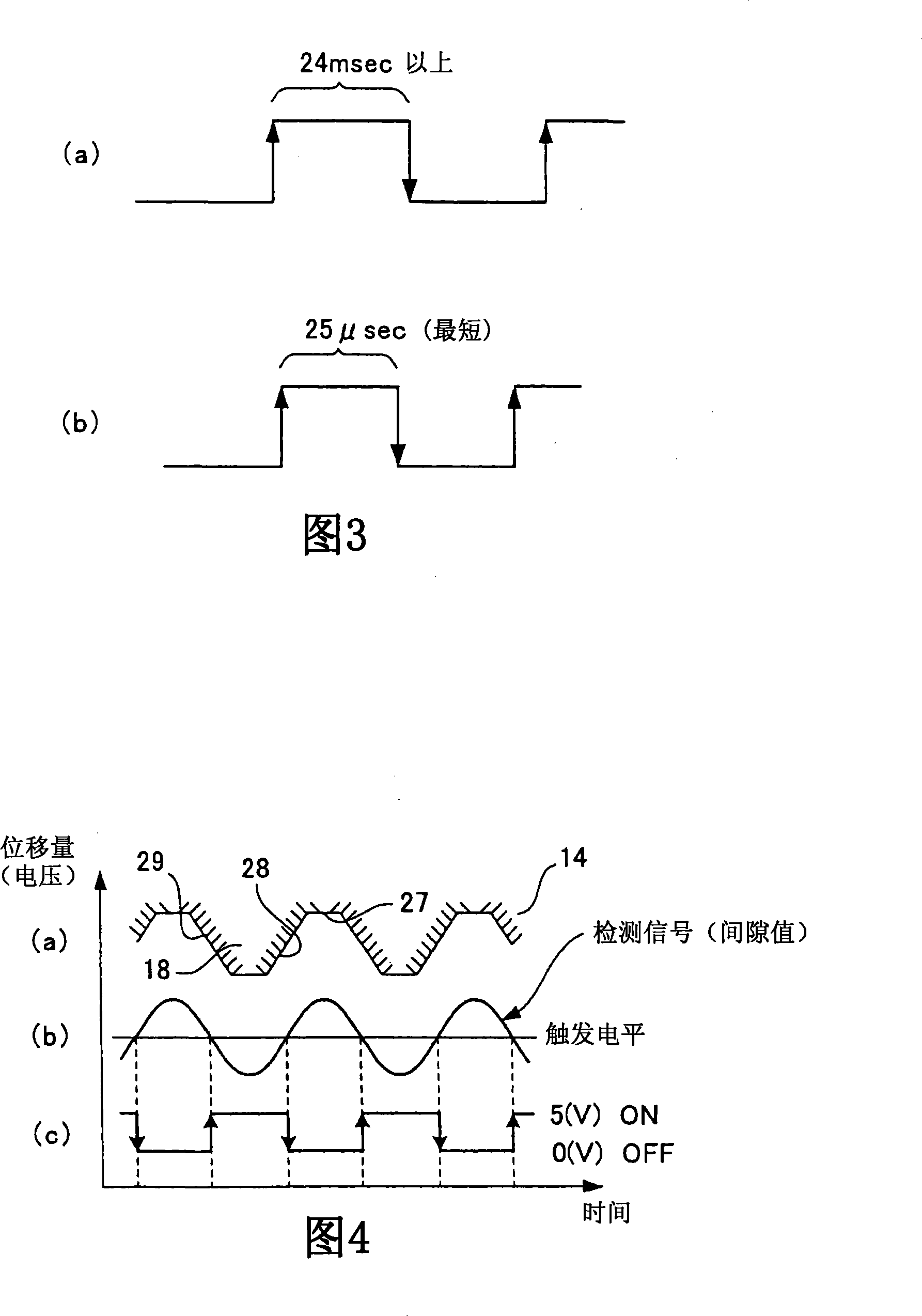
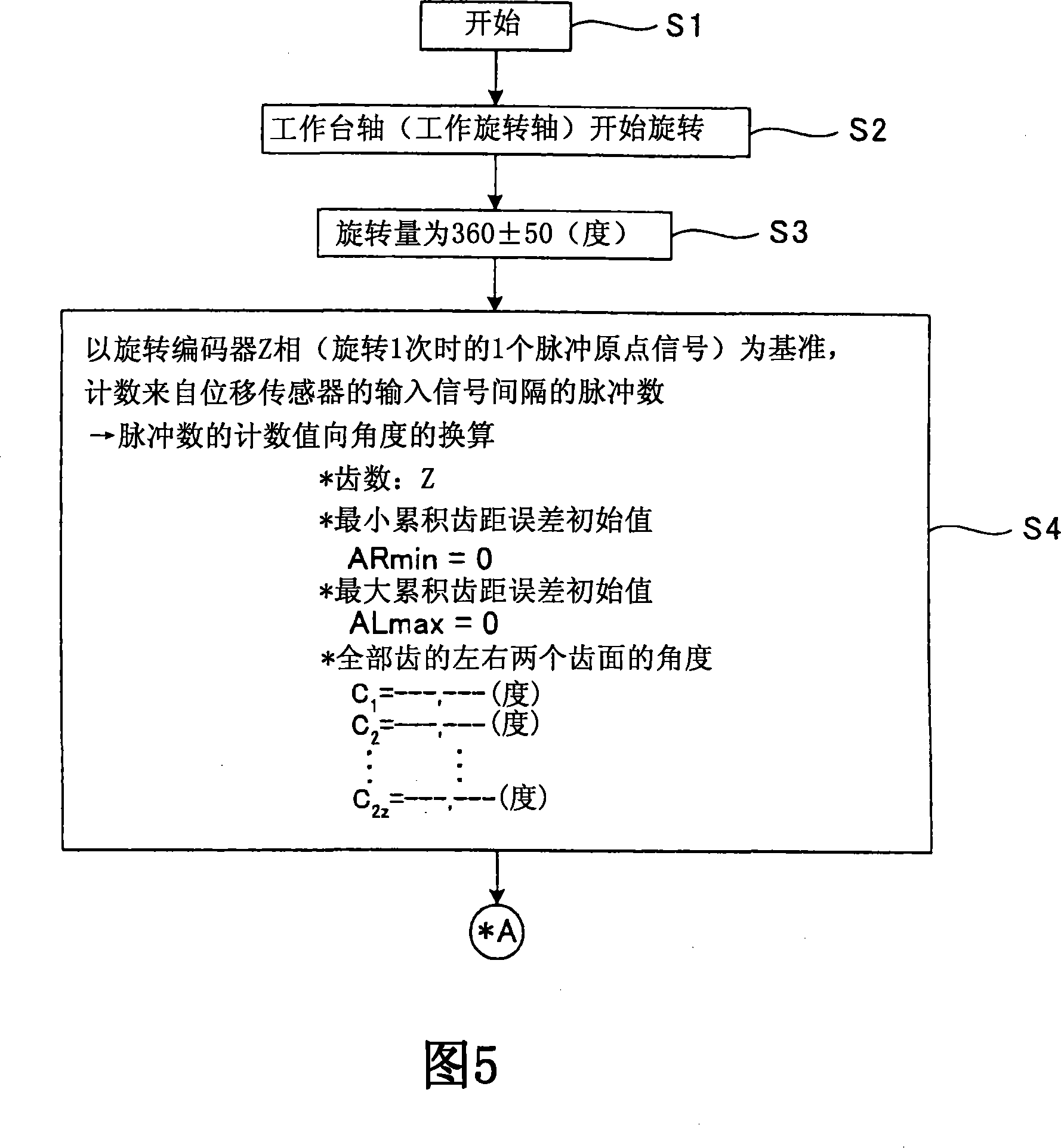
[0075] 1 is a perspective view showing the structure of main parts of a gear finishing machine such as a gear grinding machine equipped with a gear mesh angle detection device according to an embodiment of the present invention, and FIG. 2 is a block diagram showing the structure of the mesh angle detection device. 3(a) is an explanatory diagram of the signal interval (input time) that can be processed by the NC device, FIG. 3(b) is an explanatory diagram of the response speed (sampling speed) of the displacement sensor amplifier, and FIG. 4 shows the displacement An explanatory diagram showing the outline of the detection signal of the sensor head and the signal processing of the displacement sensor amplifier. 5 and 6 are flowcharts showing the flow of meshing angle detection processing. Fig. 7 is an explanatory diagram illustrati...


PUM


Abstract

The present invention provides a method and device for detecting the most suitable tooth matching angle of a gear by performing all tooth detection and its signal processing in a short time, thereby canceling the cumulative pitch errors of the left and right tooth surfaces, preventing cutting resides left on the left and right tooth surfaces, and reducing the cutting allowances of the left and right tooth surfaces to irreducible minimum values.According to the left tooth surface (28) which is most considered to leave cutting residue and having a maximum cumulative pitch error AL max (when the clockwise direction is a plus direction) and the right tooth surface(29) having a minimum cumulative error AR min (when the clockwise direction is a plus direction), these cumulative pitch errors are canceled. A correction value d for reducing the cumulative pitch errors after cutting is determined, a reference tooth groove angle 0 is corrected with the correction value d, and thus the tooth matching angle of a work gear(14) is determined.

Description

technical field [0001] The invention relates to a gear meshing angle detection method and device. Background technique [0002] A gear cut by a gear cutting machine such as a hobbing machine is further finished by a gear finishing machine such as a gear grinder. [0003] In the finishing of this gear, before the actual finishing (grinding) starts, it is necessary to carry out a "meshing" process, so that the teeth (top and bottom) of the grinding tool such as threaded grindstone and the working gear (such as hob cutting, cutting, etc.) The teeth (top and bottom) of the quenched gear) become a meshable rotational phase relationship. [0004] In addition, in this meshing process, it is necessary to obtain the meshing angle of the working gear mounted on the table shaft. As a method for obtaining the meshing angle, the following methods are included in the prior art: using a contact probe as a contact sensor A needle or a proximity sensor as a non-contact sensor detects the p...

Claims


Application Information

Patent Timeline
IPC IPC(8): G01D5/244G01D5/249G01M13/02
CPCB23F23/006B23F5/04B23F23/1218B23Q17/20
Inventor 菊池寿真石井浩
Owner MITSUBISHI HEAVY IND MACHINE TOOL CO LTD
Why Eureka
Try Eureka