Connector holder, photoelectric converter provided with connector holder, optical connector fixing structure and method for assembling connector holder

A technology of photoelectric converters and optical connectors, applied in the direction of instruments, optics, light guides, etc., can solve the problems of cumbersome operations such as fixing or removing connectors, and achieve the effects of easy disassembly, optical connection, and good fixation

Active Publication Date: 2008-05-07
THE FUJIKURA CABLE WORKS LTD
View PDF2 Cites 11 Cited by
  • Summary
  • Abstract
  • Description
  • Claims
  • Application Information

AI Technical Summary

Problems solved by technology

[0008] However, in the above configuration, there is a problem that the operati

Method used


Image

  • Connector holder, photoelectric converter provided with connector holder, optical connector fixing structure and method for assembling connector holder
  • Connector holder, photoelectric converter provided with connector holder, optical connector fixing structure and method for assembling connector holder
  • Connector holder, photoelectric converter provided with connector holder, optical connector fixing structure and method for assembling connector holder

Examples


Embodiment Construction

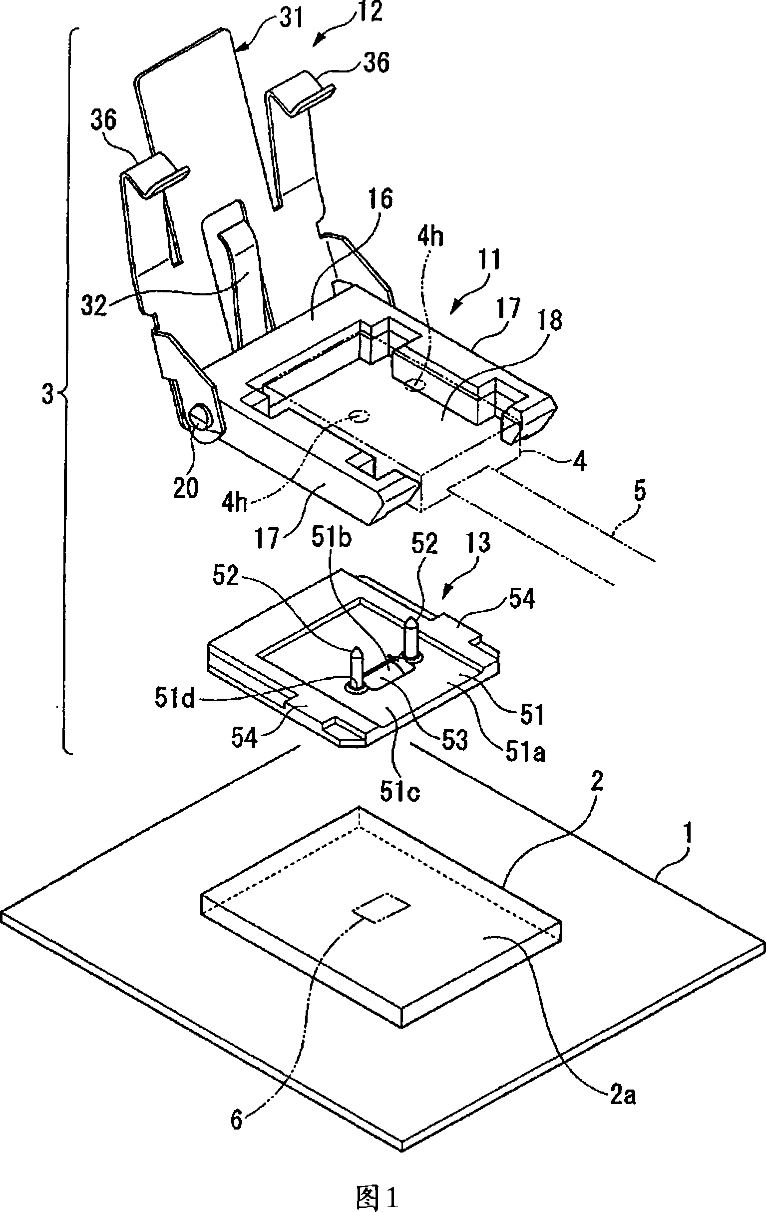
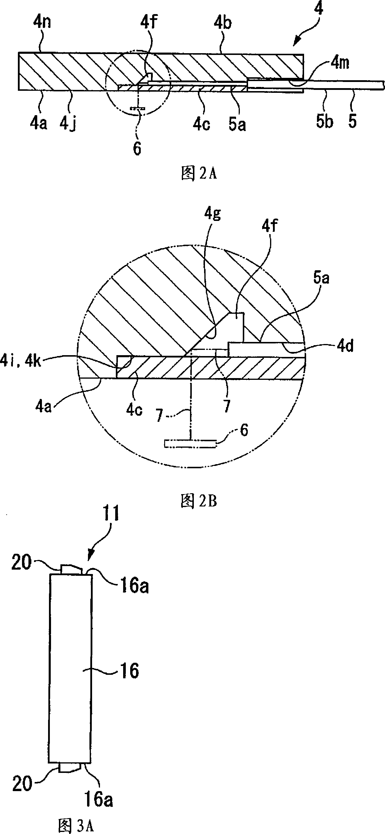
[0054] 1 is an exploded perspective view showing an example of the optical connector fixing structure of the present invention, FIG. 2A is a sectional view showing the optical connector shown in FIG. 1, and FIG. 2B is an enlarged view of main parts of FIG. 2A.

[0055]In FIGS. 1 to 10 , reference numeral 1 denotes a circuit board, 2 denotes an optical module (photoelectric converter), 3 denotes a connector holder, 4 denotes an optical connector, and 5 denotes an optical fiber.

[0056] In the present invention, the term "substrate" refers to the entire object to be mounted on which optical elements serving as optical input and output ends are mounted, and corresponds to the circuit board 1 and the optical module 2 in the illustrated example. In addition, the “photoelectric converter with connector housing” corresponds to the optical module 2 and the connector housing 3 .

[0057] (optical connector)

[0058] As shown in FIG. 1, FIG. 2A, and FIG. 2B, the optical connector 4 is...


PUM


Abstract

A connector holder fixes an optical connector assembled at a leading end of an optical fiber to an optical module having a light input/output end so that the optical fiber and the light input/output end is optically connected. The connector holder is provided with a holding section for storing at least a part of the optical connector, and a cover section attached to the holding section to be freely opened and closed. The cover section is provided with a cover section main body, and a pressing section which presses the optical connector toward the optical module.

Description

technical field [0001] The present invention relates to a structure in which an optical connector assembled at the front end of an optical fiber is fixed on a substrate provided with an optical input and output end, and the optical input and output end is optically connected to the above-mentioned optical fiber, a connector holder and a belt connector holder used therein The photoelectric converter, and the assembly method of the connector seat. [0002] This application claims priority based on Japanese Patent Application No. 2005-146698 for which it applied in Japan on May 19, 2005, and uses the content here. Background technique [0003] 15 shows a conventional optical connector fixing structure in which a connector 102 provided at the tip of an optical fiber 101 is fixed to a substrate 105 through a housing 103 and a connector mounting frame 104 (see Patent Document 1). [0004] In the connector 102 , the signal light is turned downward by the inclined surface 102 a (re...

Claims


Application Information

Patent Timeline
IPC IPC(8): G02B6/42G02B6/36
CPCG02B6/4249G02B6/4214G02B6/3897G02B6/3898G02B6/3845G02B6/4292Y10T29/49204
Inventor 藤原邦彦西村显人佐佐木健志林幸生藏田和彦吉川隆士佐佐木纯一
Owner THE FUJIKURA CABLE WORKS LTD
Why Eureka
Try Eureka