Preparing technique of back-up ring

A manufacturing process and retaining ring technology, applied in the field of standard parts manufacturing process, to achieve the effect of reducing cost, high utilization rate and high speed

Inactive Publication Date: 2008-05-14
陈福星
View PDF0 Cites 5 Cited by
  • Summary
  • Abstract
  • Description
  • Claims
  • Application Information

AI Technical Summary

Problems solved by technology

So far, there are no reports of other manufacturing processes to replace this traditional process

Method used


Image

  • Preparing technique of back-up ring

Examples


Embodiment Construction

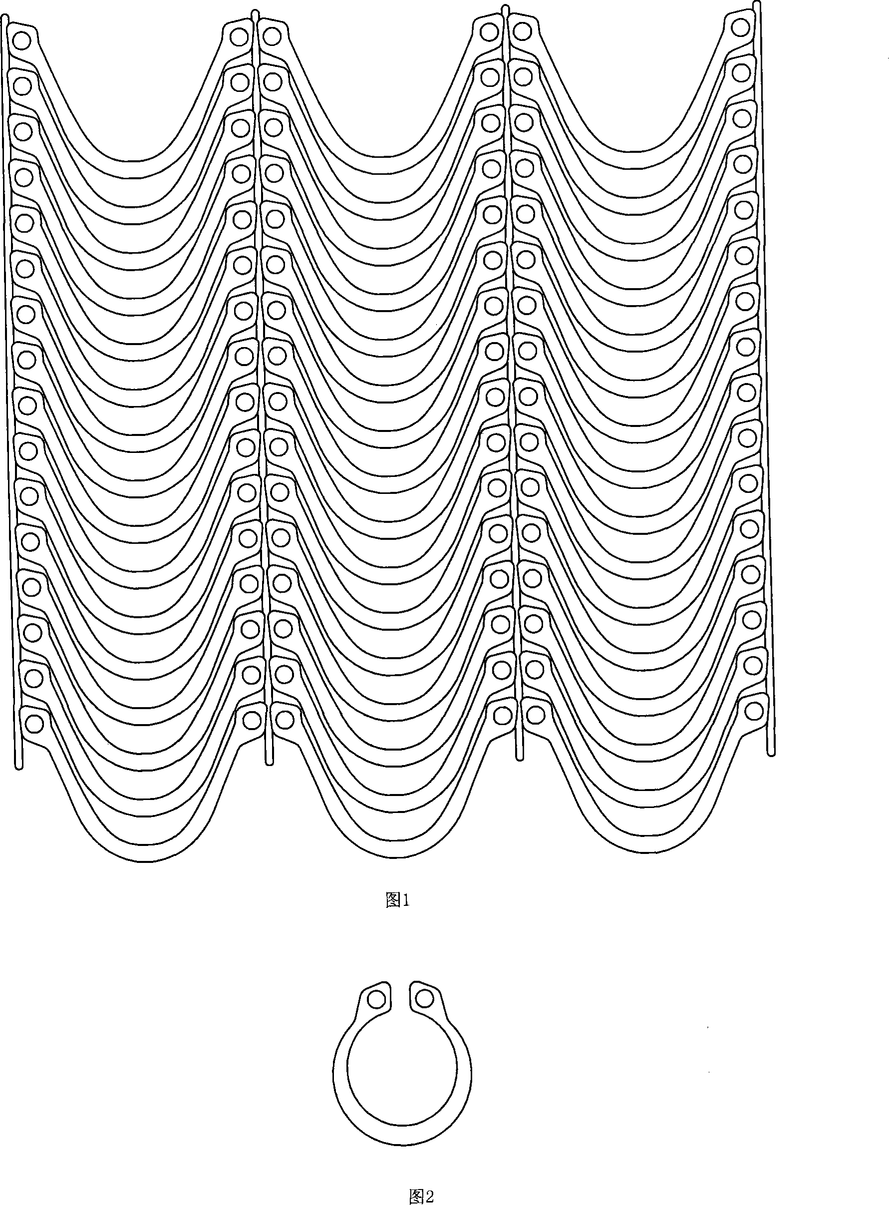
[0014] The production process of this kind of retaining ring, it first installs the mold on the punch equipment, takes the strip and puts it on the punch equipment, the strip can be iron plate or steel plate, and then uses the mold of the punch equipment to punch the strip Cut into an arc-shaped strip with a certain curvature; according to the different specifications and models of the retaining ring, the mold can be replaced, and the specifications and models are different, and the curvature of the arc-shaped strip after punching is also different; The arc-shaped strip is crimped into a circle with an opening by using a punching machine to become a retaining ring. In the above-mentioned process, the arc-shaped strips punched by the die can be wavy slats, and then the wave crests of the wavy arc-shaped strips are cut and divided to become arc-shaped strips with only one arc. Then curl the arc-shaped strips with only arcs to form retaining rings; of course, you can also directl...


PUM


Abstract

The invention discloses a manufacturing process of a retaining ring, which is characterized in that a mold is first installed on a punching machine, and after the strip is taken and placed on the punching machine, the strip is punched into a shape with a certain curvature by using the mold of the punching machine. The arc-shaped strip, and finally the arc-shaped strip with a certain curvature is curled into a circle with an opening by punching equipment, which becomes a kind of retaining ring. Adopting this technology to make the retaining ring has high speed and high safety, especially reduces material consumption by more than 30%, and will be widely used in the standard part manufacturing industry.

Description

technical field [0001] The invention relates to a manufacturing process of a standard part, in particular to a manufacturing process of a retaining ring. Background technique [0002] As a standard part, the retaining ring has a wide range of applications. It can be used in energy, electronics, electrical appliances, machinery, chemical industry, metallurgy, mold, hydraulic pressure, automobile and other industries. It can also be used as a spring gasket. At present, this kind of retaining ring is punched by a circular die on the punching machine. When punching this circular die, it is directly punched into a circle. After processing, this circle becomes a retaining ring. The inside of the circle is punched. The cut plate becomes waste, and at the same time, more circles are punched out on one plate, and the plate between the circles also becomes waste. Therefore, using this manufacturing process to make retaining rings, the utilization rate of the plate is very low. So fa...

Claims


Application Information

Patent Timeline
Patent Type & Authority Applications(China)
IPC IPC(8): B21D53/16B21D35/00B21D28/02B21D7/00
Inventor 陈福星
Owner 陈福星
Why Eureka
Try Eureka