Spillway tunnel whole-section aeration method and spillway tunnel having whole-section aeration structure

A flood tunnel and full-section technology, applied in water conservancy projects, marine engineering, coastline protection, etc., can solve the problems of side wall cavitation damage, endanger the safe operation of engineering dams, etc., and achieve the effect of avoiding cavitation damage

Inactive Publication Date: 2008-05-14
SICHUAN UNIV
View PDF0 Cites 19 Cited by
  • Summary
  • Abstract
  • Description
  • Claims
  • Application Information

AI Technical Summary

Problems solved by technology

But at present, this technology is only used at the bottom of the spillway tunnel, that is, the aeration sill is set at the bottom of the spillway tunnel, and it is matched with the ventilation shafts opened on both sides of the wall at the same position to form aeration in the bottom cavity, thus only solving the problem of the spillway tunnel The problem of cavitation damage at the bottom cannot be solved at the same time for the cavitation of the clear water area on the inner side wall at a distance downstream of the aeration sill of the high-velocity spillway tunnel, which will lead to cavitation damage of the side wall and endanger the safety of the project dam run problem

Method used


Image

  • Spillway tunnel whole-section aeration method and spillway tunnel having whole-section aeration structure
  • Spillway tunnel whole-section aeration method and spillway tunnel having whole-section aeration structure
  • Spillway tunnel whole-section aeration method and spillway tunnel having whole-section aeration structure

Examples


Embodiment 1

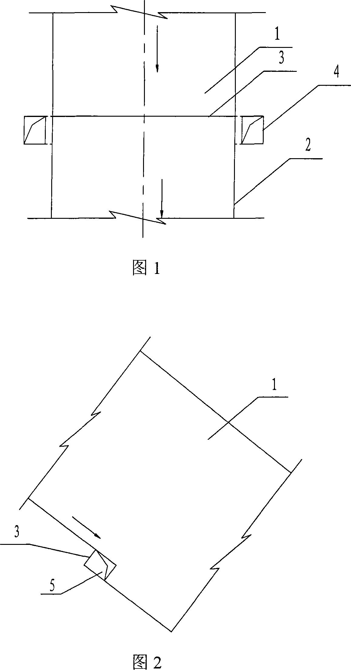
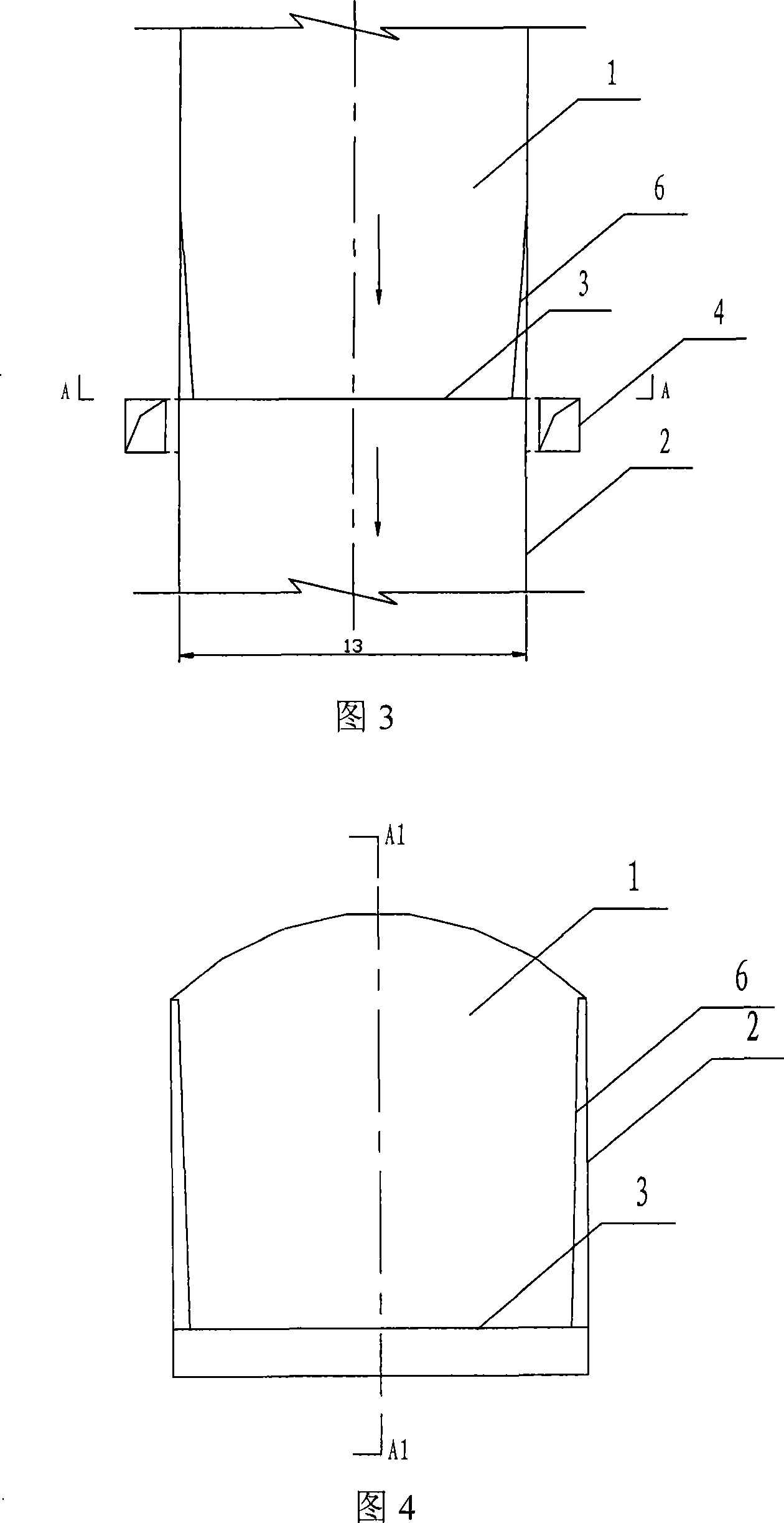
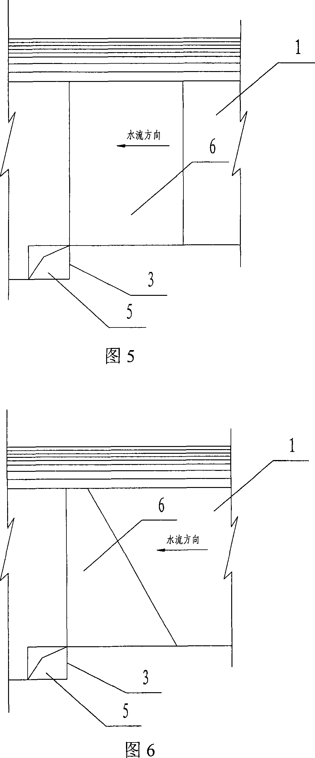
[0017] As shown in Figure 3, the flood discharge tunnel with a full-section aerated structure provided in this embodiment is provided with an aerated drop sill 3 at the bottom of the flood discharge tunnel 1, and an aerated drop sill 3 is provided outside the walls 2 on both sides of the same section of the same section. A relative "L"-shaped ventilation shaft 4, the ventilation shaft 4 communicates with the ventilation hole 5 opened on the side walls 2 on both sides of the front and bottom of the aeration drop sill 3, so that air enters the space below the front and bottom of the drop sill to form a bottom cavity for aeration. A wedge-shaped deflector 6 is respectively added on the side walls 2 on both sides of the upstream of the aerated sill 3. Thickening is formed, and its upper and lower equal widths make it form a rectangle, as shown in Figure 5, and the deflector 6 also gradually thickens from the top of the hole to the bottom of the hole to form a wedge, as shown in Fig...

Embodiment 2

[0020] As shown in Figure 3, the flood discharge tunnel with a full-section aerated structure provided in this embodiment is provided with an aerated drop sill 3 at the bottom of the flood discharge tunnel 1, and an aerated drop sill 3 is provided outside the walls 2 on both sides of the same section. A relative "L"-shaped ventilation shaft 4, the ventilation shaft 4 communicates with the ventilation hole 5 opened on the side walls 2 on both sides of the front and bottom of the aeration drop sill 3, so that air enters the space below the front and bottom of the drop sill to form a bottom cavity for aeration. A wedge-shaped deflector 6 is respectively added on the side walls 2 on both sides of the upstream of the aerated sill 3. It is formed by thickening, and the length of the upper side near the roof of the cave is smaller than the length of the bottom side. From the top side, its lower part gradually extends and widens toward the upper and lower reaches of the aeration drop s...

Embodiment 3

[0023] As shown in Figure 3, the flood discharge tunnel with a full-section aerated structure provided in this embodiment is provided with an aerated drop sill 3 at the bottom of the flood discharge tunnel 1, and an aerated drop sill 3 is provided outside the walls 2 on both sides of the same section. A relative "L"-shaped ventilation shaft 4, the ventilation shaft 4 communicates with the ventilation holes 5 opened on the side walls at the front and bottom of the aeration sill 3, so that air enters the space below the front and bottom of the sill to form the bottom cavity for aeration. A wedge-shaped deflector 6 is respectively added on the side walls 2 on both sides of the upstream of the aerated sill 3. It is formed by thickening, and the length of the upper side near the roof of the cave is zero, and its lower part gradually extends and widens toward the upper and lower reaches of the aerated sill 3 to form a triangle, as shown in Figure 7, and the deflector 6 also extends f...


PUM


Abstract

The invention discloses a whole section aeration method of a flood discharging tunnel. The bottom part of a free flow flood discharging tunnel is provided with a backward step and a ventilation shaft, which form bottom cavity aeration, based on which a lateral deflector is respectively arranged at side walls on two sides of the upstream of aeration backward step, therefore, an aeration side cavity is formed and the whole section aeration is further formed at the aeration backward step. The deflector inside the flood discharging tunnel with the whole section aeration structure designed according the method is a wedge deflector. Since the whole section aeration changes the former simplex method of bottom cavity aeration and guarantees the necessary aeration quantity when the flood discharging tunnel in normal operation, thus eliminating large-area fresh water flooding district at the side walls of the flood discharging tunnel and effectively avoiding the cavitation eroding damage of the side walls.

Description

technical field [0001] The invention belongs to the technical field of aeration and corrosion reduction in high-speed or ultra-high-speed water flow when high-head discharge structures pass through water in hydraulic engineering, and specifically relates to a full-section aeration method of a flood discharge tunnel, and a full-section aeration method designed according to the method. Spillway with cross-section aerated structure. Background technique [0002] In the past 50 years, a large number of engineering examples at home and abroad have shown that in certain parts of high and medium water head drainage buildings, when the design is not thorough or the construction is careless, the phenomenon of material erosion often occurs, that is, in concrete or The surface of the metal can cause spots and pockmarks in light cases, and form honeycomb or even large holes in severe cases (Li Jianzhong, Ning Lizhong. High-speed hydraulics. Northwestern Polytechnical University Press, 1...

Claims


Application Information

Patent Timeline
Patent Type & Authority Applications(China)
IPC IPC(8): E02B8/06
Inventor 许唯临杨永全刘善均邓军刘超肖白云黄新生王韦曲景学张建民
Owner SICHUAN UNIV
Why Eureka
Try Eureka