Light emitting module and light receiving module

A technology of light emitting module and light receiving module, applied in optics, optical elements, lenses, etc., can solve the problems of reduced light collection efficiency and inability to collect incident light, and achieve the effect of improving light collection efficiency and efficiency

Inactive Publication Date: 2008-05-14
PANASONIC CORP
View PDF2 Cites 5 Cited by
  • Summary
  • Abstract
  • Description
  • Claims
  • Application Information

AI Technical Summary

Problems solved by technology

Therefore, the light-receiving module 20 has a problem in that light collection efficiency is lowered due to a region where incident light cannot be collected.

Method used


Image

  • Light emitting module and light receiving module
  • Light emitting module and light receiving module
  • Light emitting module and light receiving module

Examples


no. 1 example

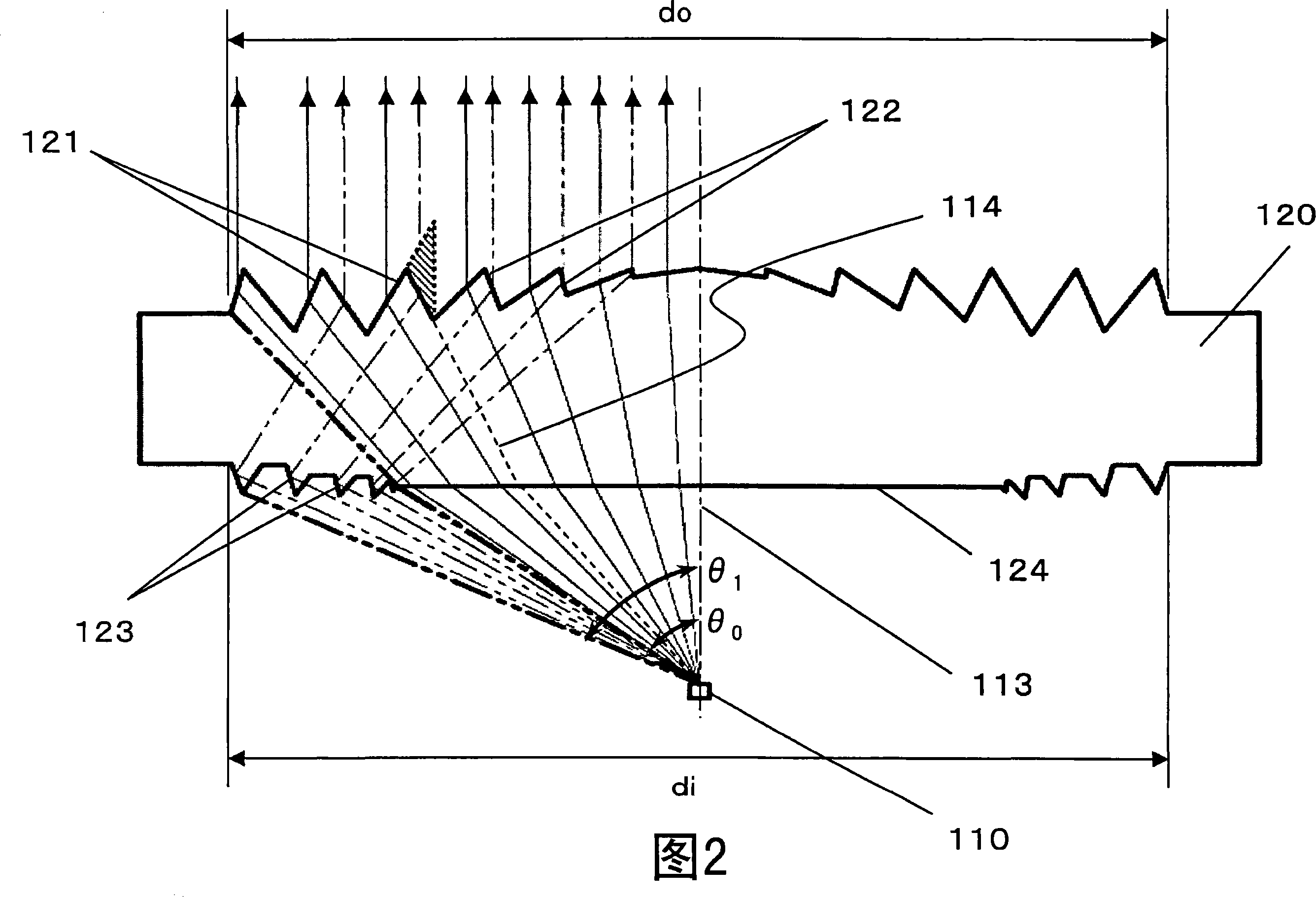
[0066] FIG. 1 is a top view and a side sectional view of a light emitting module 100 according to a first embodiment of the present invention. FIG. 2 is a side sectional view of main parts of a light emitting module 100 according to a first embodiment of the present invention.

[0067] As shown in FIGS. 1 and 2 , the light emitting module 100 mainly includes a light source 110 and a lens element 120 . As the light source 110, for example, an LED or a semiconductor laser is used. The light source 110 is housed in a package 111 . Inside the housing 130, the package 111 and the lens element 120 are fixed at positions capable of satisfying a predetermined positional relationship therebetween. The modulated electrical signal is provided via terminal 112 to light source 110 , which emits an optical signal, for example, whose luminous intensity varies according to the modulation signal, such that the optical signal spreads out from an optical axis 113 . For example, when an LED is...

no. 2 example

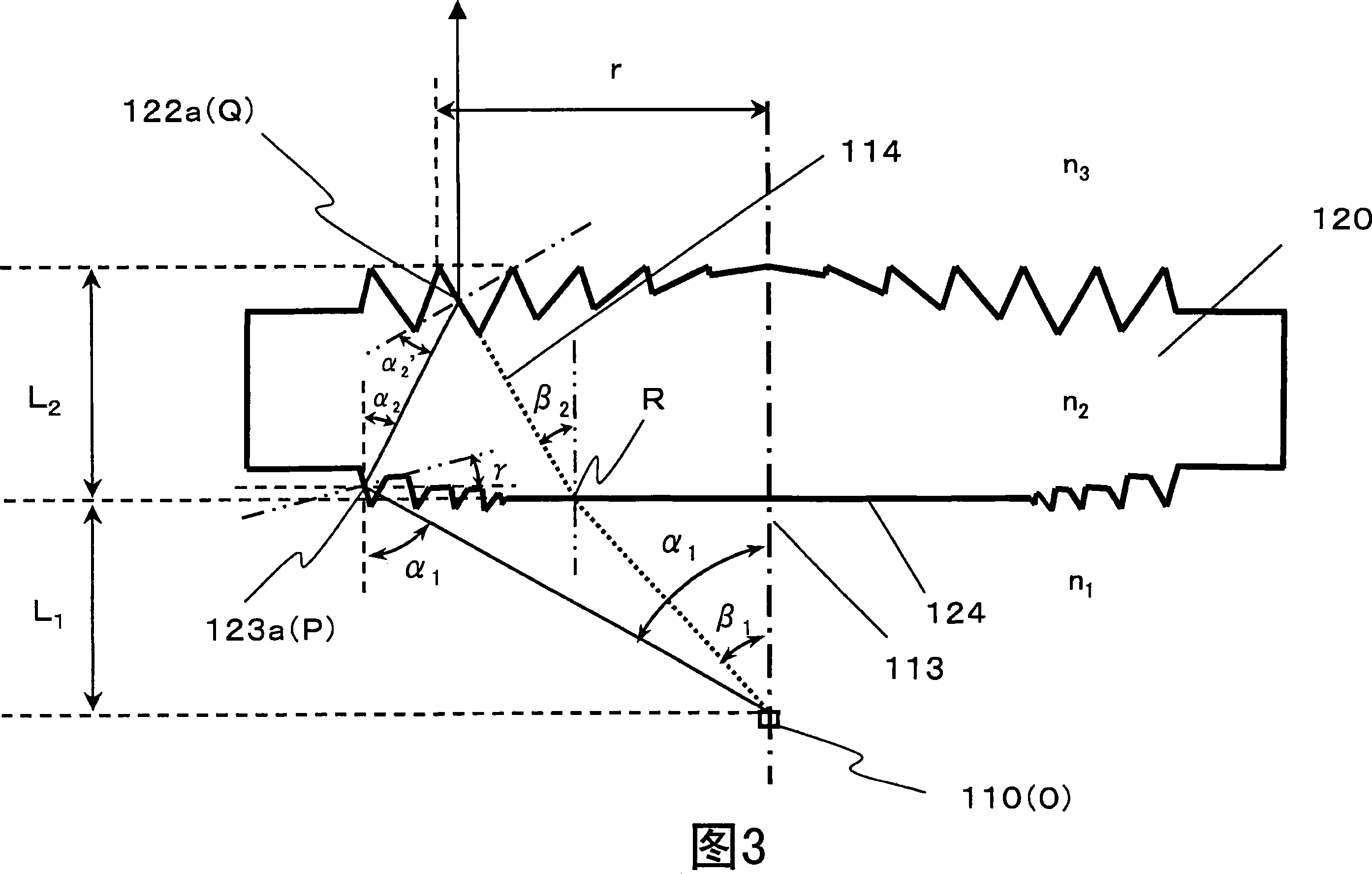
[0099] In the first embodiment, using the slave light source at θ 0 to theta 1 The emitted light at an emission angle within a range of reduces brightness variation of the emitted light, thereby realizing a light emission module with high-efficiency performance, wherein the emission angle refers to an angle between an optical axis and an emission direction. According to a second embodiment, light emitted by the light source that does not directly reach the lens element is utilized, instead of coming from the light source at θ 0 to theta 1 Light emitted at an emission angle within a range of , wherein the emission angle refers to the angle between the optical axis and the emission direction.

[0100] FIG. 10 is a top view of a light emitting module 600 according to the second embodiment of the present invention, and FIG. 11 is a side cross-sectional view of the light emitting module 600 according to the second embodiment of the present invention. FIG. 12 is a side sectional ...

no. 3 example

[0111]FIG. 19 is a top view and a side sectional view of a light receiving module 2100 according to a third embodiment of the present invention. FIG. 20 is a side sectional view of main parts of a light receiving module 2100 according to a third embodiment of the present invention.

[0112] As shown in FIGS. 19 and 20 , the light receiving module 2100 mainly includes a light receiving element 2110 and a lens element 2120 . For example, a photodiode (PD) can be employed as the light receiving element 2110 . The light receiving element 2110 is housed in a package 2111 . Inside the housing 2130, the package 2111 and the lens element 2120 are fixed at positions capable of satisfying a predetermined positional relationship therebetween. The optical receiving module 2100 receives an optical signal (for example, an optical signal transmitted by the optical transmitting module 100 of the first embodiment) from a wireless optical transmitter (not shown), which is arranged to face the...


PUM


Abstract

A plurality of first refraction surfaces (121) and a plurality of second refraction surfaces (122) are alternately provided on an emission surface of a lens element (120) so as to form concentric circles each having an optical axis (113) at the center thereof, and having diameters different from each other, and a light reflected by a plurality of reflection surfaces (123) provided on an incident surface of the lens element so as to form concentric circuits each having the optical axis (113) at the center thereof and having diameters different from each other, is refracted and emitted by the plurality of second refraction surfaces (122) at desired angles. Therefore, it is possible to enhance efficiency and an emission intensity, and reduce variations in brightness of an emitted light without increasing the diameter of the lens element (120), thereby realizing a light emitting module (100) enabling advantageous performance.

Description

technical field [0001] The present invention relates to an optical transmitting module and an optical receiving module respectively used in, for example, a wireless optical transmitter and a wireless optical receiver in a wireless optical transmission system for transmitting such as video data, audio signals through free space Information data as optical signals of digital data signals, and more particularly, the present invention relates to a light emitting module capable of reducing brightness variation (variation) of emitted light and improving efficiency, and a light receiving module having improved light collection efficiency . Background technique [0002] An advantageous feature of the wireless optical transmission system for transmitting optical signals through free space is that, since light enables broadband transmission, transmission can be performed at a higher speed than radio transmission using radio waves. To incorporate a wireless optical transmitter and a w...

Claims


Application Information

Patent Timeline
Patent Type & Authority Applications(China)
IPC IPC(8): G02B3/00G02B27/00H01L33/54H01L33/56H01L33/60H01L33/62
Inventor 家田知明笹井裕之
Owner PANASONIC CORP
Why Eureka
Try Eureka