
Safety evaluation method of high-temperature production facility or component defect

A technology for safety evaluation and production equipment, applied in the direction of instruments, computer control, simulators, etc., can solve the problems of equipment reliability reduction, waste, structural cracks, etc., and achieve the effect of reducing workload

Inactive Publication Date: 2008-05-14
EAST CHINA UNIV OF SCI & TECH
View PDF4 Cites 25 Cited by
  • Summary
  • Abstract
  • Description
  • Claims
  • Application Information

AI Technical Summary

Problems solved by technology

Patent CN1477383A "Testing method for creep life of high-temperature components" provides a creep life prediction method considering high-temperature aging factors, but does not consider the influence of pre-cracks, so it is not suitable for safety evaluation of damage caused by cracks
Other patents such as CN101038248A "A Method and System for Predicting Creep Life of High-temperature Turbine Components", CN86103018A "Method for Determining Remaining Effective Life of Turbine Components" and CN1908974A "On-line Evaluation and Prediction Method for Calendar Life of High-temperature Durable Parts of Steam Turbine" etc. It is a prediction method based on damage theory for the life and safety of operating steam turbine components. It does not consider creep fracture and crack factors, so it cannot handle the evaluation of defects found in engineering inspections.
However, in practice, defects such as cracks in the structure are unavoidable, and simple parking maintenance and scrapping will cause unnecessary waste and directly lead to the consequence of reducing the reliability of the equipment

Method used


Image

  • Safety evaluation method of high-temperature production facility or component defect
  • Safety evaluation method of high-temperature production facility or component defect
  • Safety evaluation method of high-temperature production facility or component defect

Examples


Embodiment

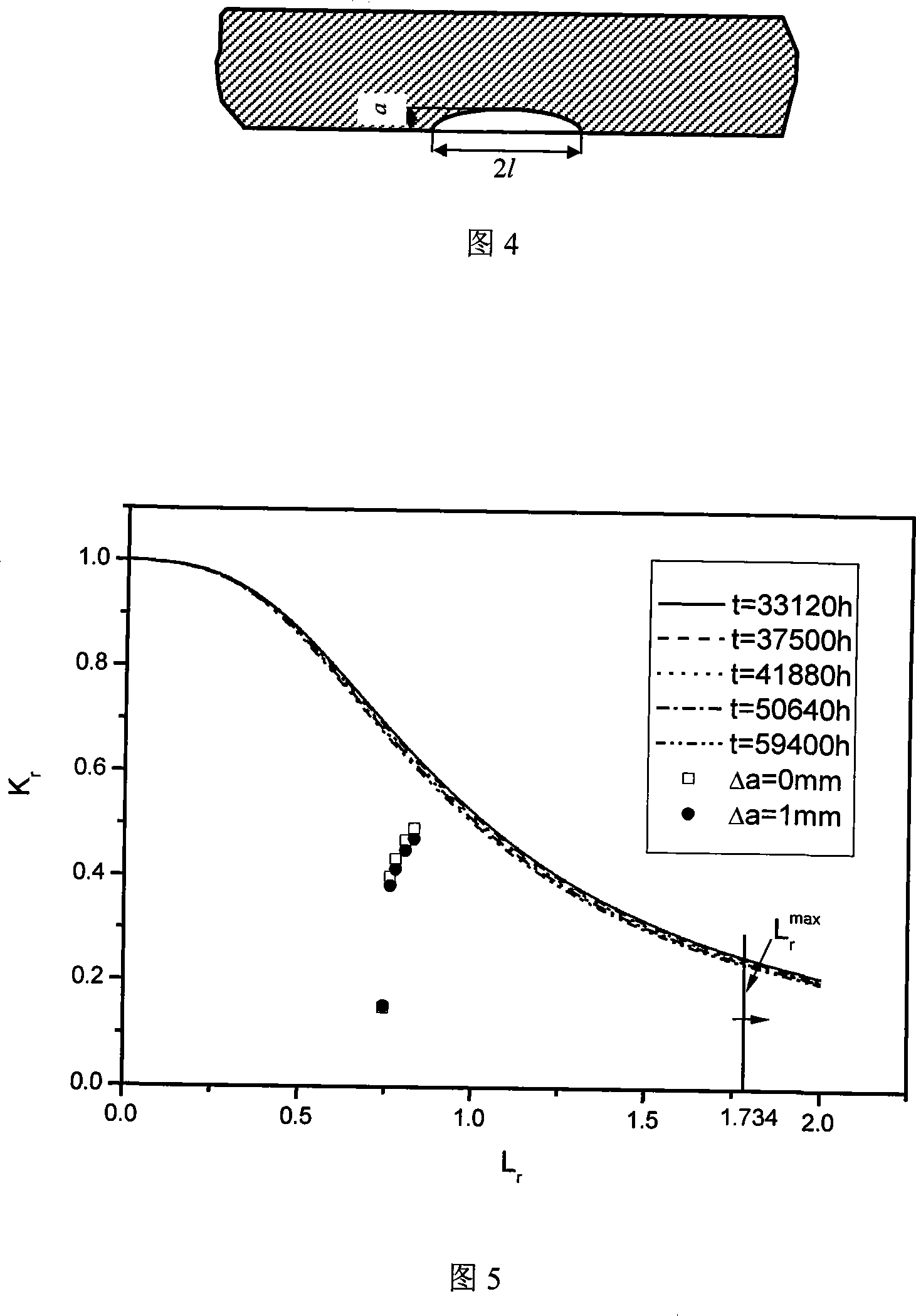
[0059] A key reaction equipment in a refinery was put into operation in November 1996. During a routine inspection in September 2000, a crack was found on the cylinder of the equipment. The crack is located on the inner surface of the cylinder with an inner diameter of 2800mm and a wall thickness of 45mm, distributed radially and perpendicular to the wall. The cracks were away from the weld, and there were no obvious signs of stress corrosion cracking during inspection. Due to the limitations of the production process, the equipment needs to continue to operate for one year before it can be overhauled. From being put into operation to finding cracks, the reactor has worked for a total of 33120 hours. Calculated as 365 days a year, the reactor needs to continue to run for 8760 hours.

[0060] In order to ensure the reliability of the operation of the reactor within one year thereafter, the safety evaluation method of the present invention is adopted, and the time-related fail...


PUM


Abstract

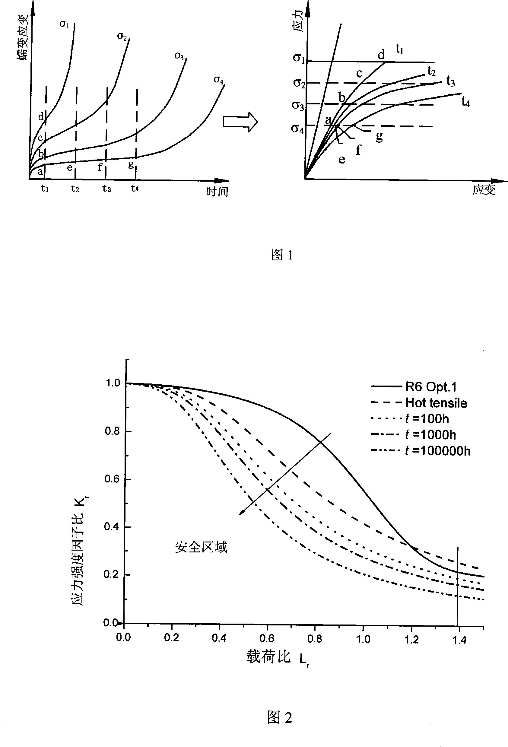
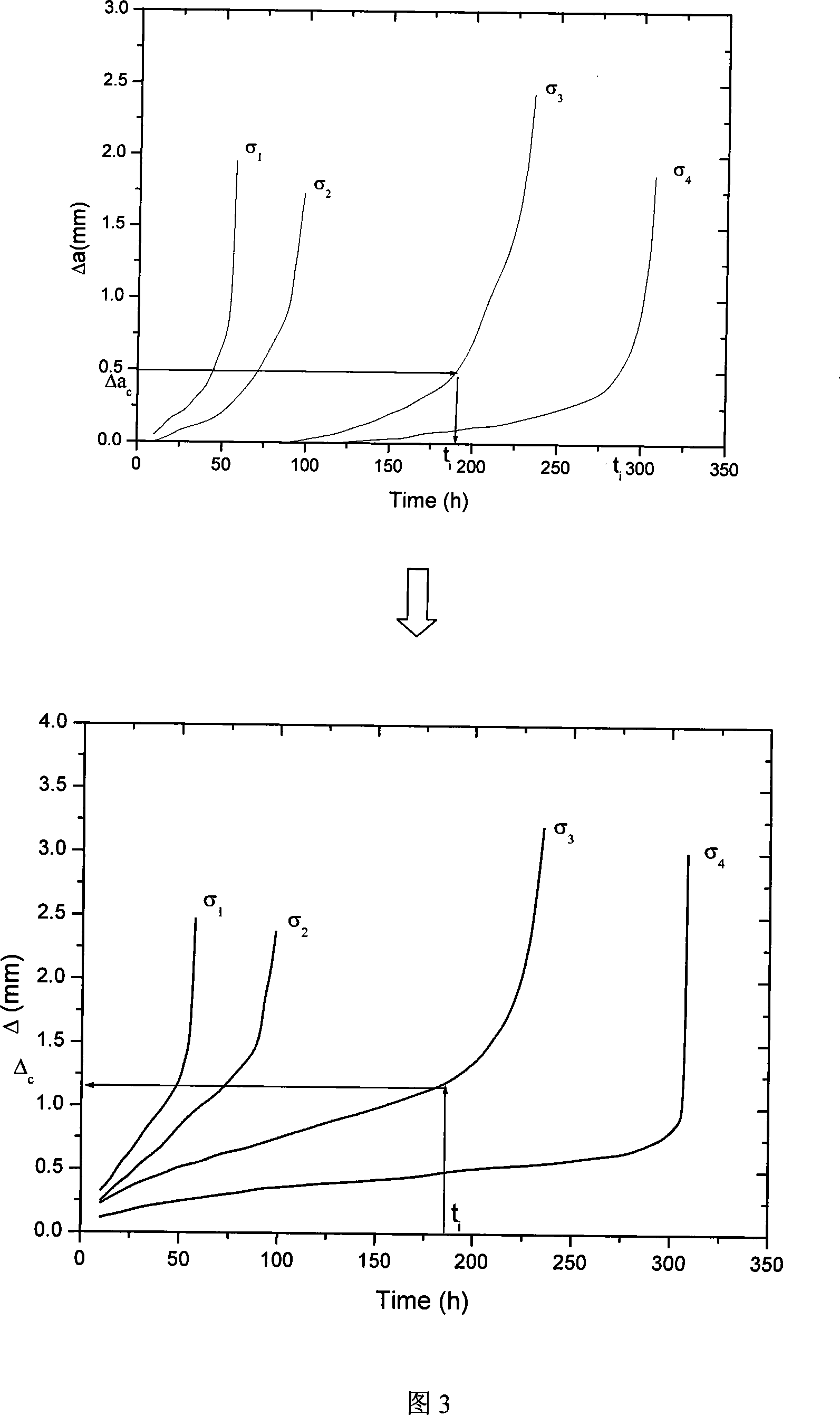
The invention discloses a safety evaluation method for the shortcomings of a high temperature production device or part, comprising the steps as follows: a creep strain-time curve of the material of the high temperature production device or part at a particular temperature is obtained, and an isochronous stress-strain curve corresponding to the particular time is established based on the creep strain-time curve; a failure assessment curve chart related to time is established; and a parameter Kr which can determine and reflect the cracking failure degree of the part and a parameter Lr which can determine and reflect the ultimate load failure degree of the part are counted; and finally the parameters(Kr and Lr) are put into the failure assessment chart as state points for comparing so as to determine the failure assessment point and judge the safety of the failure assessment point. The method can be used for analyzing the safety of the shortcomings during the production process and the use process of the high temperature production device or part, thereby avoiding unnecessary maintenance and premium, and further increasing the rationality of making maintenance plans for high temperature production devices.

Description

technical field [0001] The invention belongs to the technical field of safety engineering, and in particular relates to a safety evaluation method for defects in high-temperature production equipment or components, especially a method for identifying whether creep fracture failure occurs in production equipment or components used in high-temperature environments after defects are found. Safety management and control of high temperature production equipment. Background technique [0002] Pressure vessels, steam turbines, boilers, steam pipelines and other equipment operating in high-temperature environments will inevitably have defects during service and manufacturing. Creep deformation and creep damage are one of the main factors leading to their failure, so how to evaluate It is of great significance to identify whether this type of equipment can be damaged by creep failure to ensure safe production. For the safety evaluation of equipment defects in the normal temperature ...

Claims


Application Information

Patent Timeline
IPC IPC(8): G05B19/048
Inventor 轩福贞涂善东王正东
Owner EAST CHINA UNIV OF SCI & TECH
Learn More