Light-emitting circuit board based on surface-mounted LED devices

A technology for LED devices and light-emitting circuits, which is applied to printed circuits connected to non-printed electrical components, cooling/heating devices of lighting devices, light sources, etc. Life attenuation and other problems, to achieve the effect of improving the heat dissipation effect, reducing the contact area and improving the light efficiency

Inactive Publication Date: 2016-01-20
广东良得光电科技有限公司
View PDF4 Cites 0 Cited by
  • Summary
  • Abstract
  • Description
  • Claims
  • Application Information

AI Technical Summary

Problems solved by technology

The LED can convert electricity into light. Its structure is to place LED chips on a bracket, connect the positive and negative poles of the power supply through the bracket, and package the entire LED with a light-transmitting sheet made of epoxy resin fingers. Problem: Due to the certain resistance of the LED chip itself, a certain amount of heat will be generated in the state of power on and illuminated, and the heat will gather around the LED chip for a long time. The fluorescent powder accelerates the loss and attenuates the life of the LED; and the structure of the bracket is not conducive to the directional reflection of the light source, which wastes the light from the light source and reduces the light efficiency.

Method used


Image

  • Light-emitting circuit board based on surface-mounted LED devices
  • Light-emitting circuit board based on surface-mounted LED devices
  • Light-emitting circuit board based on surface-mounted LED devices

Examples


Embodiment Construction

[0024] In order to make the object, technical solution and advantages of the present invention clearer, the present invention will be further described in detail below in conjunction with the accompanying drawings.

[0025] refer to figure 1 , figure 2 , image 3 , Figure 4 The structural representation of the present invention shown.

[0026] The embodiment of the present invention provides a light-emitting circuit board based on a surface-mounted LED device,

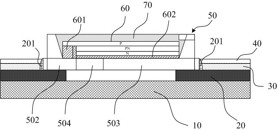
[0027] The LED light-emitting board includes the bottom circuit board base layer 10, a conductive layer 20 mounted on the circuit board base layer 10, a surface-mounted LED device 50 connected to the conductive layer 20 through solder 201, and a surface-mounted LED device 50 covering the conductive layer 20. The top paint 30, the light-transmitting paint 40 coated on the top paint 30; the conductive layer 20 is a copper clad laminate layer with a circuit design, and the top paint 30 is a milky white reflective pa...


PUM


Abstract

The embodiment of the invention discloses a luminous circuit board of an LED (Light Emitting Diode) device based on surface mounting. The luminous circuit board comprises a circuit board base layer, a conducting layer arranged on the circuit board basic layer and finish coat covering on the conducting layer. The LED device comprises an insulated frame body, a positive wafer and a negative wafer, wherein the frame body is internally provided with a polarity dividing strip which is used for dividing the frame body into a hollow positive region and a hollow negative region, and the positive wafer and the negative wafer are respectively arranged at the bottoms of the positive region and the negative region; the positive wafer and the negative wafer are electrically connected with the conducting layer; and an inner inclined wall is arranged between the upper frame surface and the lower frame surface of the frame body. The inner wall of a frame is changed into the inner inclined wall so that the light sources of LEDs are effectively reflected out, the thickness of the frame is reduced, the exposure area of an LED chip is increased, the luminous efficiency of a manufactured LED lamp is greatly improved, light rays are reflected out under the effect of the fitting finish coat and light transmittance coat, and color temperature is increased.

Description

technical field [0001] The invention relates to an LED lighting circuit board structure, in particular to a light-emitting circuit board based on surface-mounted LED devices. Background technique [0002] Because LED lights have the advantages of small size, low power consumption, long service life, high brightness, low heat, environmental protection, and durability, LED lights are becoming more and more popular. The LED can convert electricity into light. Its structure is to place LED chips on a bracket, connect the positive and negative poles of the power supply through the bracket, and package the entire LED with a light-transmitting sheet made of epoxy resin fingers. Problem: Due to the certain resistance of the LED chip itself, a certain amount of heat will be generated in the state of power on and illuminated, and the heat will gather around the LED chip for a long time. The consumption of the fluorescent powder is accelerated, so that the life of the LED is attenuate...

Claims


Application Information

Patent Timeline
Patent Type & Authority Patents(China)
IPC IPC(8): H05K1/18F21V29/503F21V29/508F21Y101/02
Inventor 苏松得
Owner 广东良得光电科技有限公司
Why Eureka
Try Eureka