Ventilation flap with orientation and flow rate adjustment obtained by rotating a profiled body

A ventilation device and main body technology, applied in space heating and ventilation details, transportation and packaging, heating methods, etc., can solve problems such as impossible to be used, difficult ventilation devices, etc., and achieve the effect of accurate flow rate

Inactive Publication Date: 2010-05-19
法雷西亚内地工业公司
View PDF6 Cites 0 Cited by
  • Summary
  • Abstract
  • Description
  • Claims
  • Application Information

AI Technical Summary

Problems solved by technology

[0006] The advantages of low head loss and low ventilation noise are obtained, but there is a problem that due to the extreme length of the ventilation device, it is difficult and sometimes impossible to use the ventilation device in the instrument panel of the vehicle

Method used


Image

  • Ventilation flap with orientation and flow rate adjustment obtained by rotating a profiled body
  • Ventilation flap with orientation and flow rate adjustment obtained by rotating a profiled body
  • Ventilation flap with orientation and flow rate adjustment obtained by rotating a profiled body

Examples


Embodiment Construction

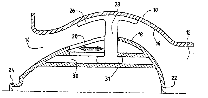
[0056] figure 1 is a half cross-sectional view of the ventilation device according to the first embodiment of the present invention.

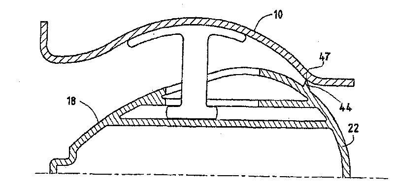
[0057] The ventilation device comprises a duct 10 forming a cavity between an inlet opening 12 and an outlet opening 14 . A portion of the inner surface 16 of the duct 10 is spherically segmented.

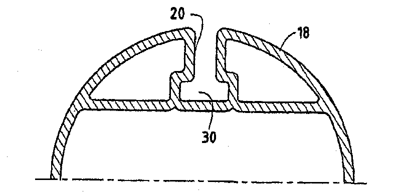
[0058] Inside the duct cavity, the shaped body 18 has a longitudinal slit 20 between its spherical inlet portion 22 and an operating member 24 formed at its outlet end.

[0059] The outer surface of an annular member 26 forms a spherical section having the same radius as the spherical section of the inner surface 16 of the pipe 10 along which the annular member can slide. The annular part 26 comprises at least one arm 28 , preferably three, protruding towards the inside in the slit 20 of the shaped body, terminating at a groove 30 of the shaped body 18 . This groove is shown extending longitudinally, but it can also have a different orientation, ...


PUM


Abstract

The invention concerns a swivel joint ventilation flap comprising an air stream duct (10), a profiled body (18) the major part of which is at least arranged in the duct chamber, and a ring (26) co-operating with the duct and with the profiled member so that it supports the profiled body (18) in the duct while enabling the profiled body to be moved relative to the duct. Part at least of the inner surface of the chamber forms a spherical segment, the ring (26) has an outer surface forming a sphere portion of practically the same radius as the spherical segment of the chamber, and the ring (26) is arranged in the chamber at the outer surface of the profiled body (18). The profiled body (18) can slide relative to the ring (26). The ventilation flap is suitable for motor vehicle instrument panels.

Description

technical field [0001] The present invention relates to a ventilation device intended to direct an air flow, such as air of conditioned temperature and humidity, while allowing the direction and flow rate of the air flow to be adjusted according to the needs of the user. [0002] Such ventilation devices are particularly designed for vehicles in which a recirculation circuit of air flows to the ventilation device, which in turn delivers an air flow having a direction and flow rate selected by the user. Background technique [0003] According to document FR-2872260, which was published only after the priority date of this specification, a ventilating device with adjustment of the direction of the air flow has been disclosed, which has an air flow duct with a first part between the inlet and the outlet of the duct, The first part forms a hemispherical cavity with a gradually changing cross-section, and also has a spherically truncated second part. The shaped body is accommoda...

Claims


Application Information

Patent Timeline
Patent Type & Authority Patents(China)
IPC IPC(8): F24F13/065F24F13/10B60H1/34
CPCB60H1/3442B60H1/3414F24F13/065
Inventor L·弗南德斯P·古雷罗G·赫里奎特E·弗兰科伊斯C·布兰彻里奥
Owner 法雷西亚内地工业公司
Why Eureka
Try Eureka