Optical hair removing device

一种脱毛装置、光线的技术,应用在洗涤头发或头皮的装置、光疗法、医药科学等方向,能够解决难以确定照射单元与皮肤紧密接触等问题,达到减轻负担、避免间隙泄漏的效果

Inactive Publication Date: 2008-05-21
MATSUSHITA DENKO KK
View PDF0 Cites 23 Cited by
  • Summary
  • Abstract
  • Description
  • Claims
  • Application Information

AI Technical Summary

Problems solved by technology

However, in the prior art, it is difficult to determine that the irradiation unit is in close contact with the skin

Method used


Image

  • Optical hair removing device
  • Optical hair removing device
  • Optical hair removing device

Examples


Embodiment Construction

[0021] Hereinafter, the embodiments of the present invention will be described in detail with reference to the drawings constituting a part of the embodiments of the present invention.

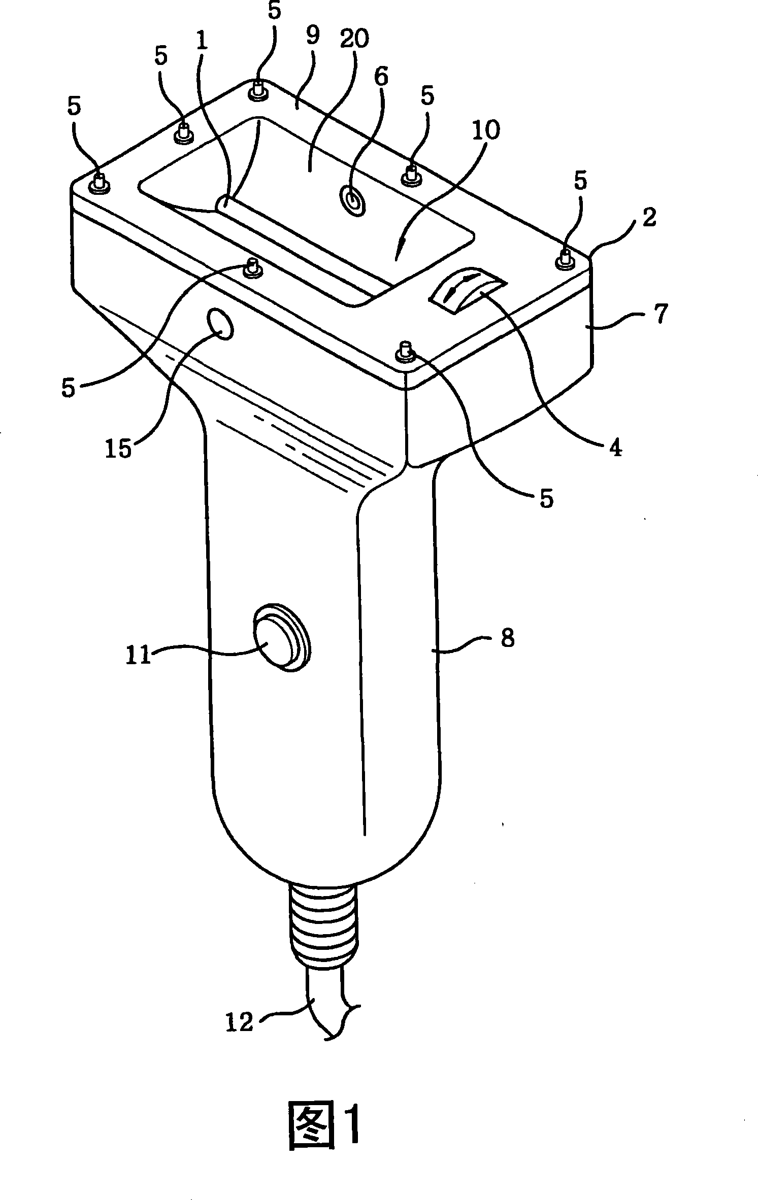
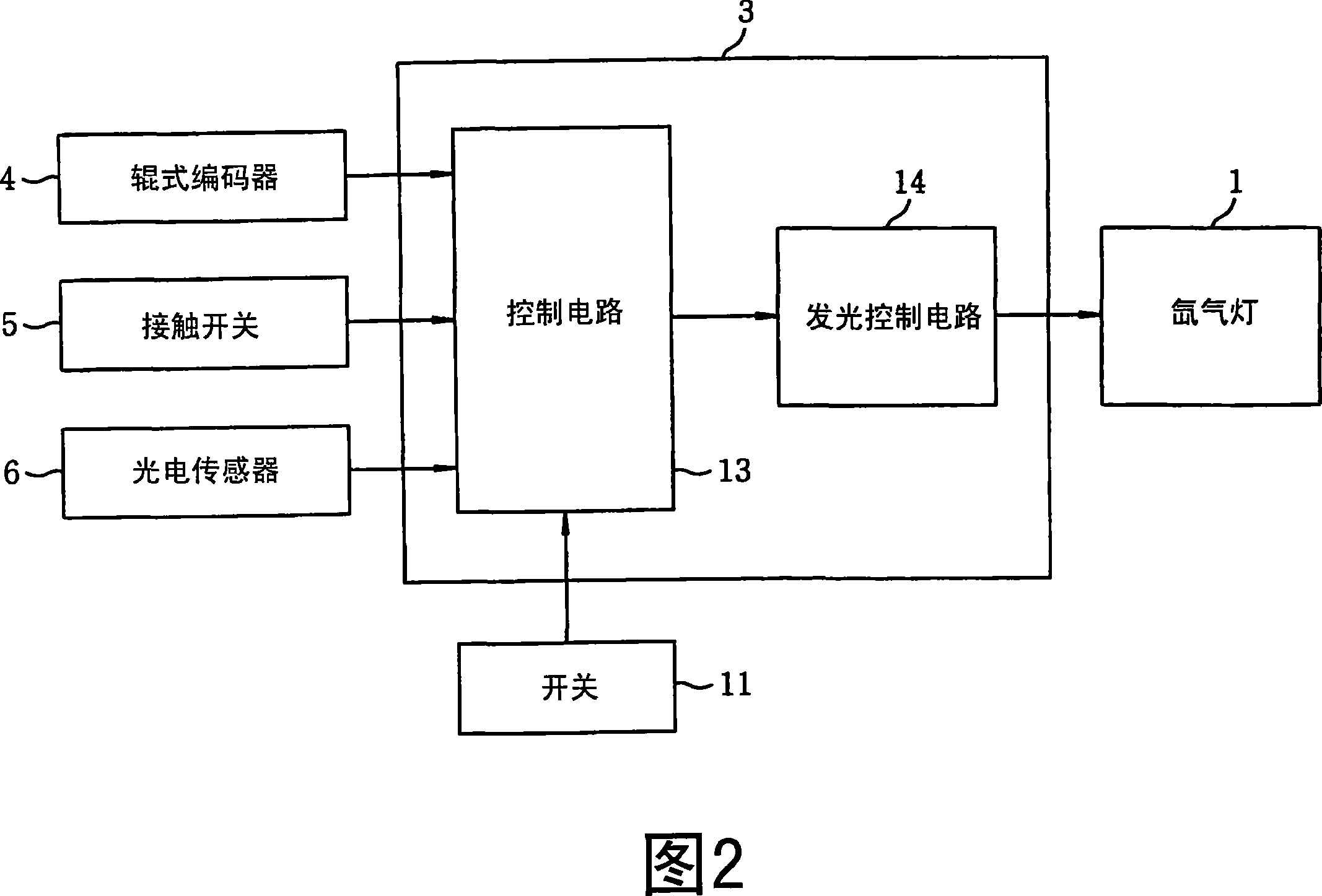
[0022] Figures 1 and 2 show an optical hair removal device according to an embodiment of the present invention. As shown in Figures 1 and 2, the optical hair removal device includes: a light-emitting unit 1 for emitting light, such as a xenon lamp, etc.; an irradiating unit 2 for irradiating the light emitted by the xenon lamp 1 to body hair on the skin; The control unit 3 for the emission of the xenon lamp 1. The irradiation unit 2 has a movement detection unit 4 for detecting movement of the irradiation unit 2 on the skin, such as a roller encoder, etc.; and a contact switch 5, which serves as a contact detection for detecting contact between the irradiation unit 2 and the skin unit.

[0023] A light detection unit 6 such as a photoelectric sensor or the like is installed in the irradiation unit...


PUM


Abstract

An optical hair removing device includes a light emitting unit (1) for emitting a light and an irradiation unit (2) for irradiating the light emitted from the light emitting unit to body hairs on a skin. Further, the optical hair removing device includes a control unit (3) for controlling the light emission unit (1). The irradiation unit (2) has a movement detection unit (4) for detecting a movement of the irradiation unit on a skin and a contact detection unit (5) for detecting a contact between the irradiation unit and the skin.

Description

Technical field [0001] The present invention relates to an optical hair removal device for removing body hair on the skin by irradiating light to the body hair on the skin. Background technique [0002] The conventional optical hair removal device includes a laser source for emitting a laser beam, an irradiation unit for irradiating the laser beam emitted from the laser source to body hair on the skin, and a device for moving the irradiation unit along the contour of the skin in the X and Y directions. A moving mechanism and a control unit for controlling the moving mechanism. [0003] The body hair is automatically removed by moving the irradiation unit on the skin in the X or Y direction within a specified range using a moving mechanism controlled by the control unit (for example, see Japanese Patent Laid-Open No. 2002-172179). [0004] However, since the moving mechanism in the optical hair removal device described in the above patent application moves the irradiation unit wit...

Claims


Application Information

Patent Timeline
Patent Type & Authority Applications(China)
IPC IPC(8): A45D26/00A61N5/06
CPCA61B2018/00476A61B18/203A61B2018/1807A45D26/00A61B2019/409A61B2019/465A45D26/0009A61B2017/00026A61B2018/00452A61B2090/049A61B2090/065A61N5/06
Inventor 大川和己
Owner MATSUSHITA DENKO KK
Why Eureka
Try Eureka