Dual cyclone dust collection structure of suction cleaner dust collection barrel

A technology of dust collection barrels and vacuum cleaners, applied in the direction of suction filters, etc., can solve the problems of poor filtering effect, small dust collection centrifugal force, low suction rate, etc., and achieve the effect of improving suction rate and dust collection effect

Inactive Publication Date: 2008-05-21
LG ELECTRONICS (TIANJIN) APPLIANCES CO LTD
View PDF0 Cites 3 Cited by
  • Summary
  • Abstract
  • Description
  • Claims
  • Application Information

AI Technical Summary

Problems solved by technology

[0009] Aiming at the above-mentioned problems that the dust collection bucket of the vacuum cleaner in the prior art has a small cyclone dust collection centrifugal force, low suction rate, and poor filtering effect, the present invention introduces a dust collection bucket with a new structural design. The turbine-type fan blade device inside makes the cyclone regenerate in the dust collecting bucket. In this way, through the offset air inlet on the bucket body and the turbine-type fan blade device installed in the dust collecting bucket, both the air intake and the outlet air of the dust collection bucket can be generated. Cyclone with consistent power, double cyclone improves suction rate and dust collection effect

Method used


Image

  • Dual cyclone dust collection structure of suction cleaner dust collection barrel
  • Dual cyclone dust collection structure of suction cleaner dust collection barrel
  • Dual cyclone dust collection structure of suction cleaner dust collection barrel

Examples


Embodiment Construction

[0022] The specific embodiment of the present invention will be further described in conjunction with the accompanying drawings.

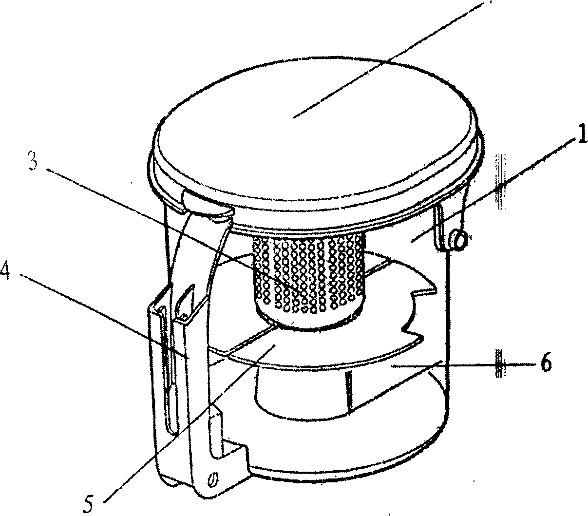
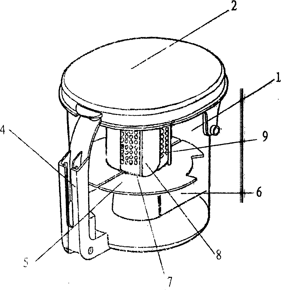
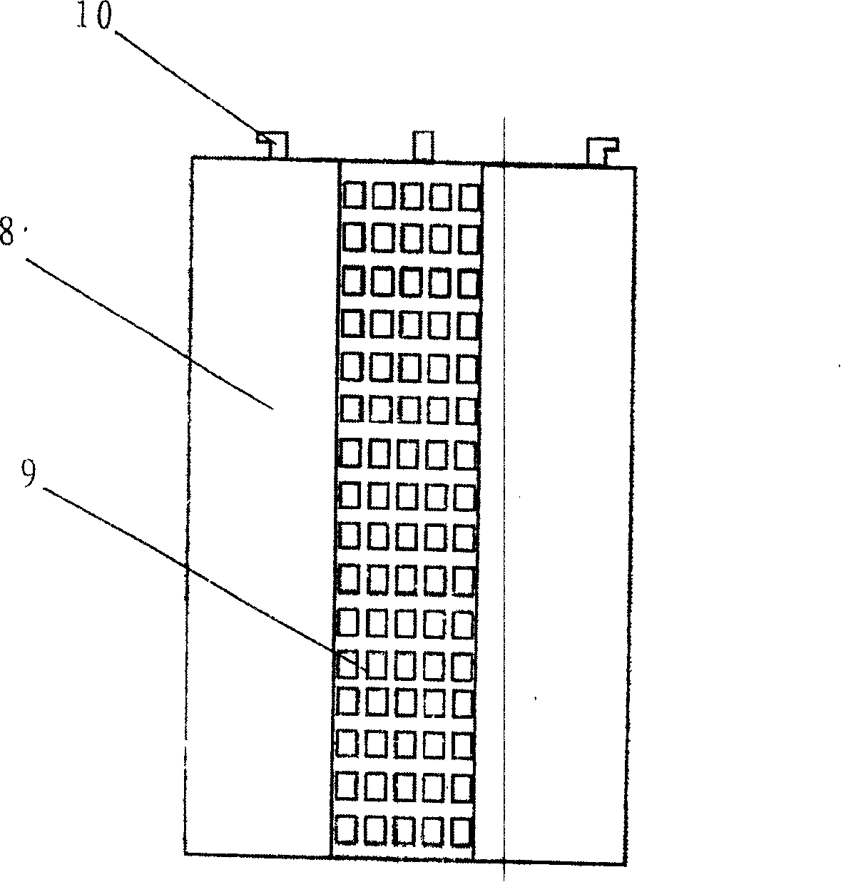
[0023] figure 2 Show the structure of the vacuum cleaner dust bucket involved in the present invention, image 3 and Figure 4 A side view and a top view of the turbine fan blade device in the dust collecting barrel of the vacuum cleaner involved in the present invention are respectively shown.

[0024] As shown in the figure, the dust collecting bucket of the vacuum cleaner involved in the present invention is cylindrical, and is composed of a bucket body 1 , a bucket cover 2 and a turbine fan device 7 . The bucket cover 2 is buckled on the bucket body 1, and a turbine fan blade device 7 is arranged in the bucket body 1. The inner cavity of the barrel is divided into upper and lower parts by a partition plate 5, the upper part is provided with a turbine fan device 7, and the lower part is provided with an air outlet duct 6. The turbine fan bl...


PUM


Abstract

The invention relates to a dual-cyclone dust collection structure of a dust collection tub of a cleaner, comprising an air inlet which is slantingly arranged at the tub body of a dust collection tub and a turbo-typed fan blade device which is arranged inside the dust collection tub, wherein, the device is formed by a plurality of fan blades which are arranged at the framework of a cylindraceous filter screen; the top and the bottom of the framework of the screen are corresponding round reels and the screen between the top round reel and the bottom round reel takes a shape of cylinder and four fan blades are vertically positioned between the top round reel and the bottom round reel; the upper end of the turbo-typed fan blade device is fixed at a tub cover of the dust collection tub by a card; the interior of the cylindraceous filter screen is communicated with an air outlet duct at the lower part of a split plate. Cyclones generated by air-in and air-out parts of the dust collection tub have even strength and the dual cyclone improves the absorption rate of the cleaner so as to increase centrifugal force of dust in the air, which results in that much more dust is thrown to the wall of the tub and falls along clearance in the margin to the lower part of the tub, thus improving the effect of dust collection.

Description

technical field [0001] The invention relates to a vacuum cleaner, in particular to a dust collecting bucket of the vacuum cleaner. Background technique [0002] The vacuum cleaner is a household appliance for indoor cleaning and hygiene, which is used to remove dust from the ground, carpets, walls, furniture and various gaps. Generally speaking, a vacuum cleaner mainly includes a suction device and a suction pipeline. The suction device mainly formed by a motor and a fan is arranged in the body. The suction pipeline includes a suction head and a suction pipe. The air port communicates with the air inlet of the fan inside the body through the telescopic pipe and flexible pipe of the suction pipe. When the vacuum cleaner is running, the motor drives the impeller of the fan to rotate at a high speed, exhausting the air in the vacuum cleaner, forming an instantaneous vacuum in the vacuum cleaner, and forming a relatively high negative pressure difference with the outside atmosp...

Claims


Application Information

Patent Timeline
Patent Type & Authority Applications(China)
IPC IPC(8): A47L9/16
Inventor 李艳君
Owner LG ELECTRONICS (TIANJIN) APPLIANCES CO LTD
Why Eureka
Try Eureka