Flood discharging and energy dissipating device

A technology for energy dissipation and flood discharge, which is applied in water conservancy projects, sea area engineering, coastline protection, etc. It can solve the problems of large discharge flow energy and scouring of the bottom of dams, etc., and achieve the effect of improving energy dissipation efficiency

Inactive Publication Date: 2008-05-21
CHINA HYDROELECTRIC ENGINEERING CONSULTING GROUP CHENGDU RESEARCH HYDROELECTRIC INVESTIGATION DESIGN AND INSTITUTE
View PDF0 Cites 15 Cited by
  • Summary
  • Abstract
  • Description
  • Claims
  • Application Information

AI Technical Summary

Problems solved by technology

Later, the "X" type wide tail energy dissipation pier set up in the flood discharge channel appeared. There is a certain distance, so that two flow states of underflow and longitudinal stretching water flow are formed, so that it can better adapt to the incoming flow of different flows. There are two flow states of extrusive flow, and the energy of the flood discharge flow is still very large, resulting in scouring of the bottom of the dam

Method used


Image

  • Flood discharging and energy dissipating device
  • Flood discharging and energy dissipating device
  • Flood discharging and energy dissipating device

Examples


Embodiment 1

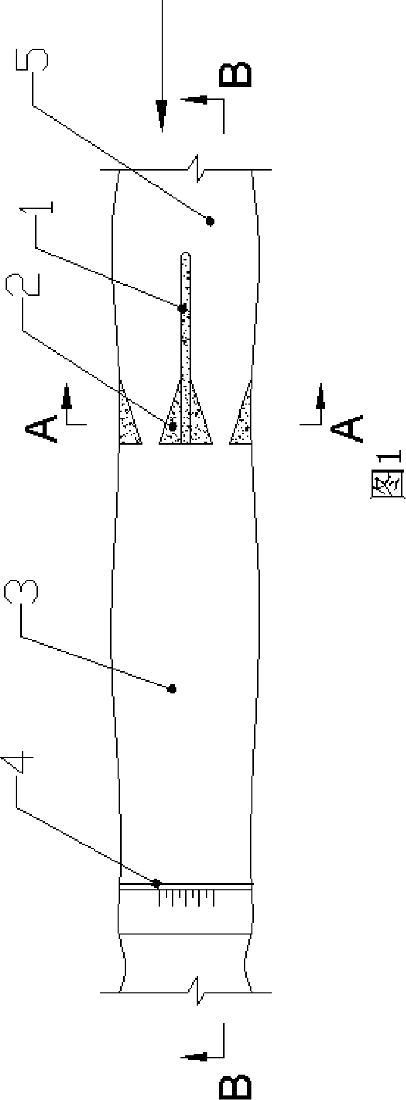
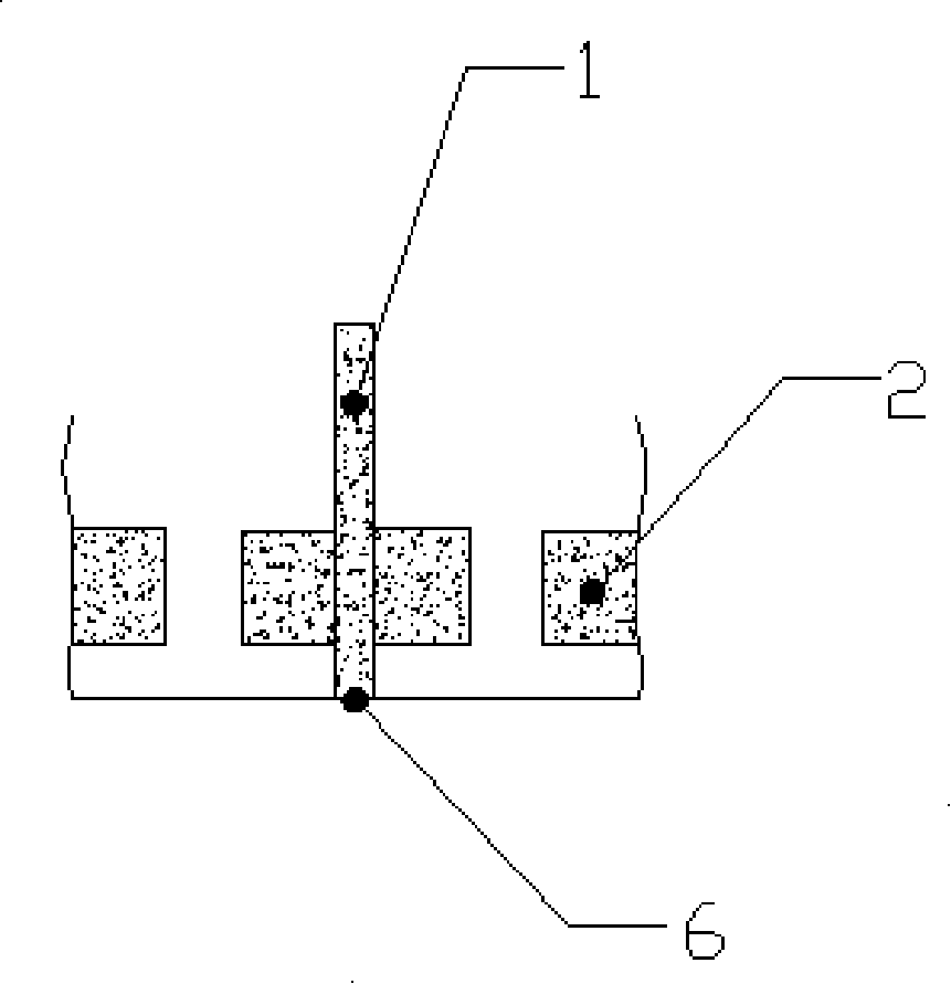
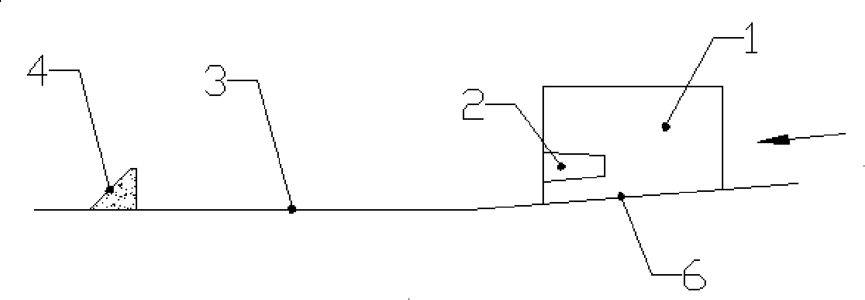
[0017] Example 1: The bottom slope of the downstream section of a project spillway tunnel is 0.1, the width is 15m, and the discharge flow is 600m 3 / s~2800m 3 / s, the terminal velocity is 27m / s~35m / s. Adopt energy dissipater described in the present invention, its arrangement form is as shown in Fig. 1~ image 3 shown. A wide tail energy dissipation pier 2 is installed at the end of the spillway tunnel. The bottom of the pier body is parallel to the spillway tunnel, 1.5m away from the bottom of the spillway tunnel. The height of the pier gradually increases from 2.5m to 3.0m. The length of the pier body is 7.5m. The angle is 4°, the shrinkage ratio of the wide tail energy dissipation pier 2 is 0.28, and the height from the lower surface to the runner surface 6 is 0.25 times of the maximum flood discharge depth. The downstream stilling basin 3 is equal width stilling basin, the width of the stilling basin 3 is 15m, the length is 60m, and the end of the rear stilling basin i...

Embodiment 2

[0018] Embodiment 2: On the basis of Embodiment 1, set the protruding angle on the upper surface of the wide-tail energy dissipation pier 2 to -10°, the shrinkage ratio to 0.2, and the height from the lower surface to the runner surface 6 to be 0.2 times the maximum flood discharge depth . At this time, there is also a better energy dissipation effect, but compared with Example 1, the energy dissipation rate is reduced.

Embodiment 3

[0019] Embodiment 3: On the basis of Embodiment 1, the angle of the upper surface of the wide tail energy dissipation pier 2 is set to 15°, the shrinkage ratio is set to 0.5, and the height from the lower surface to the runner surface 6 is 0.3 times of the maximum flood discharge depth. The energy dissipation effect at this time is equivalent to that of Embodiment 1, but due to the increase of the protruding angle, the length of the stilling pool 3 is extended accordingly.


PUM


Abstract

The invention discloses a flood discharge energy dissipater in a flood discharge channel and can promote the flood discharge energy dissipation efficiency of a water conservancy dam or a hydropower dam. The flood discharge energy dissipater comprises a flood discharge channel equipped with separation piers. The separation piers are equipped with wide-tail energy dissipation piers, the width of which gets bigger along the water flow direction. The bottom of the wide-tail energy piers and the channel surface of the flood discharge channel are separated with a certain distance. The top of the wide-tail energy dissipation piers is equipped with a bevel of minus 10 to 15 degrees, so the top acts as a water passing area and a water tongue jetting from the top jets freely and then flows out of the dam. Thus, the water flow forms an energy dissipation model of the free water jetting plus the longitudinally stretched water flowing plus the bottom flowing, so the water flows are fully mixed outside the dam to promote the energy dissipation efficiency to over 50 percent. The invention is applicable in all large, medium and small water-flow water-conservancy dams and hydropower dams.

Description

technical field [0001] The invention relates to an energy dissipation device used in water conservancy and hydropower projects, in particular to a flood discharge energy dissipation device used in a flood discharge channel. Background technique [0002] At present, the problem of energy dissipation of large flow and low Floyd's number water flow has always been one of the key points and difficulties in the research of hydraulics and hydraulics. At present, there are two main methods commonly used at home and abroad: one is to set up auxiliary energy dissipation in the stilling pool In order to prevent cavitation damage of auxiliary energy dissipation workers, this method is generally only applicable to low-head drainage structures (such as Qinghai Xuelongtan Power Station); the second is to use wide tail piers to add force dissipation This method is generally used in discharge structures with medium and high heads (such as Yantan Power Station, Gaobazhou Power Station, etc.)...

Claims


Application Information

Patent Timeline
Patent Type & Authority Applications(China)
IPC IPC(8): E02B8/06
Inventor 田忠余挺王仁坤肖富任周鸿汉
Owner CHINA HYDROELECTRIC ENGINEERING CONSULTING GROUP CHENGDU RESEARCH HYDROELECTRIC INVESTIGATION DESIGN AND INSTITUTE
Why Eureka
Try Eureka