
Gas valve online quick-speed leak detection method

A valve and fast technology, applied in the field of detection, can solve the problems of affecting continuous and stable gas supply, wasting energy, low sensitivity, etc., and achieve the effect of increasing implementation frequency, reducing labor costs, and high accuracy and sensitivity

Active Publication Date: 2011-06-29
GUANGZHOU GAS +1
View PDF0 Cites 1 Cited by
  • Summary
  • Abstract
  • Description
  • Claims
  • Application Information

AI Technical Summary

Problems solved by technology

This method has disadvantages such as low sensitivity, long time consumption, waste of energy, pollution of the environment, and influence on continuous and stable gas supply.

Method used


Image

  • Gas valve online quick-speed leak detection method
  • Gas valve online quick-speed leak detection method

Examples


Embodiment 1

[0026] (1) Maintain a certain pressure difference on both sides of the valve

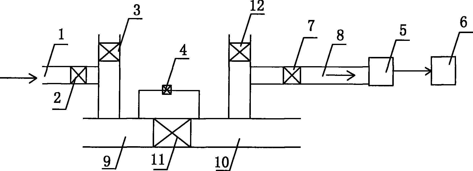
[0027] In the case of normal gas supply, close the valve and maintain a certain pressure difference on both sides of the valve, as shown in Figure 1, keep P1>P2, and select the difference between P1 and P2 as 0.02Mpa.

[0028] (2) adding tracer gas;

[0029] Add tracer gas at the P1 side of the higher pressure side, and the amount of tracer gas added is 20000-21000g.

[0030] The tracer substance must be inert, not easy to auto-oxidize, non-corrosive, safe, and not affect the gas quality. The tracer substance must also not exist in the gas, and is a gas at normal temperature and pressure, so as to meet the analysis requirements. Through the screening of a large number of substances, the applicant selected ether substances as the tracer gas. After the applicant's long-term and large amount of experiments, one by one gas was checked, and dimethyl ether was first selected as the tracer gas.

[0031...

Embodiment 2

[0038] The operation steps are the same as in Example 1, the difference between P1 and P2 on both sides of the valve is kept at 0.05Mpa, and a tracer gas is added to the P1 end on the side with higher pressure, and the amount of tracer gas added is 80g-100g. Other operations are the same as in Example 1, the tracer gas is collected and enriched, and analyzed by gas chromatography.

Embodiment 3

[0040] (1) Maintain a certain pressure difference on both sides of the valve

[0041] In the case of normal air supply, close the valve and maintain a certain pressure difference on both sides of the valve, as shown in Figure 1, keep P1>P2, and keep the difference between P1 and P2 at 0.03-0.04Mpa.

[0042] (2) adding tracer gas;

[0043] Add tracer gas at the P1 end of the side with higher pressure, and the amount of tracer gas added is 200g-300g.

[0044] The tracer substance must be inert, not easy to auto-oxidize, non-corrosive, safe, and not affect the gas quality. The tracer substance must also not exist in the gas, and is a gas at normal temperature and pressure, so as to meet the analysis requirements. Through the screening of a large number of substances, the applicant selected ether substances as the tracer gas. After the applicant's long-term and large amount of experiments, one by one gas was checked, and dimethyl ether was first selected as the tracer gas.

[...


PUM


Abstract

The invention discloses an online rapid leak detection method for a fuel gas valve. Appropriate trace gas is selected and the certain pressure difference of the two sides of the valve can be maintained, moreover, trace gas is added into one side of the valve; the other side of the valve collects and enriches trace gas; an appropriate method is selected to detect the trace gas; the detected resultis adopted to determine whether the valve has inner leakage or not. The method of the invention has high accuracy and sensitivity, when in the inner leakage detection of the valve, gas stopping and fuel gas discharging cannot be conducted, with safety, environmental protection, energy saving, time saving and fuel gas saving; the invention can effectively improve implementation frequency and increase the safety of fuel gas production, transmission and distribution as well as gas utilization by the user; moreover, the invention can match with a vehicle-mounted gas chromatographic instrument andrealize the complete, continuous and systemic detection of the whole fuel gas transmission and distribution system.

Description

technical field [0001] The invention relates to a detection method, in particular to an online rapid leak detection method for a gas valve. Background technique [0002] The gas valve is an important facility of the gas pipeline network. It plays the role of isolating the gas of different media or cutting off the gas transmission. If the valve is not closed tightly, the internal leakage will cause gas channeling, which will seriously affect the safe production and safe use. In order to ensure the safety of gas production and users, it is necessary to check and find the internal leakage of the valve in time. [0003] At present, the commonly used online detection method for valves is to maintain a certain pressure on one side of the valve, and exhaust the gas on the other side to reduce the pressure to close to zero gauge pressure. By observing the pressure change on the low pressure side, it is judged whether the valve is internally leaking. This method has disadvantages su...

Claims


Application Information

Patent Timeline
Patent Type & Authority Patents(China)
IPC IPC(8): G01M3/22
Inventor 许俊城温浩胜袁金彪伍波李秀怀李军卞淞霖张逸伟廖能林东恩
Owner GUANGZHOU GAS
Learn More