
Optical point-checking device correcting instrument

A point-to-point and calibration technology, applied in the field of surveying and mapping instruments, can solve the problems of the point-pointing device being unable to be calibrated, having no versatility, and high labor intensity, achieving flexible and stable rotation and braking, high labor intensity, and reduced labor intensity. Effect

Inactive Publication Date: 2008-05-21
赵雷 +1
View PDF0 Cites 8 Cited by
  • Summary
  • Abstract
  • Description
  • Claims
  • Application Information

AI Technical Summary

Problems solved by technology

[0003] 1. The collimated light tube fixed calibration method is forcibly correcting the tested optical plummet. This method is limited by the structure of the light tube. When the light tube reticle is subject to vibration and other factors, the tested optical plummet cannot be corrected.
not universal
[0004] 2. The actual observation method needs to place the instrument on the tripod and operate according to the procedures of the instrument. The operator must have rich experience and stand for a long time.
When testing multiple instruments, there are disadvantages such as high labor intensity, time-consuming, and laborious

Method used


Image

  • Optical point-checking device correcting instrument
  • Optical point-checking device correcting instrument
  • Optical point-checking device correcting instrument

Examples


Embodiment Construction

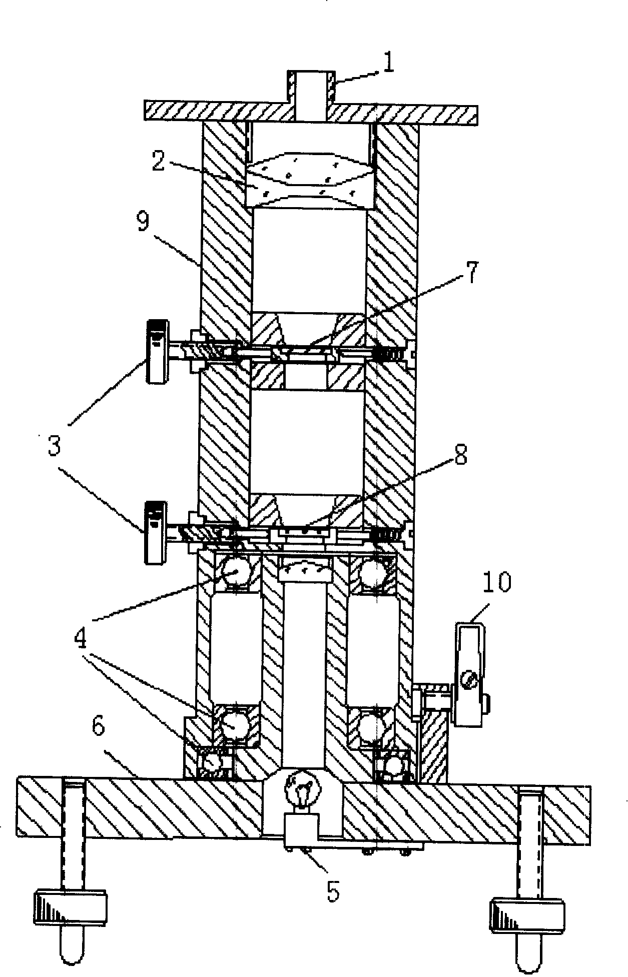
[0031] 1. Hold the theodolite, align the central screw hole at the bottom of the theodolite with the M16 screw on the upper part of the calibrator, turn the optical tube to tighten it, and roughly level the theodolite so that the optical axis of the optical plummet enters the optical tube of the calibrator. The operator sits in front of the calibration instrument. During the calibration process, the eyepiece of the optical plummet is facing the operator, and the 6v power supply is connected.

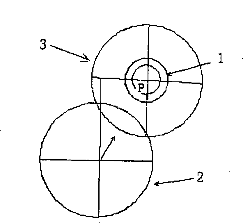
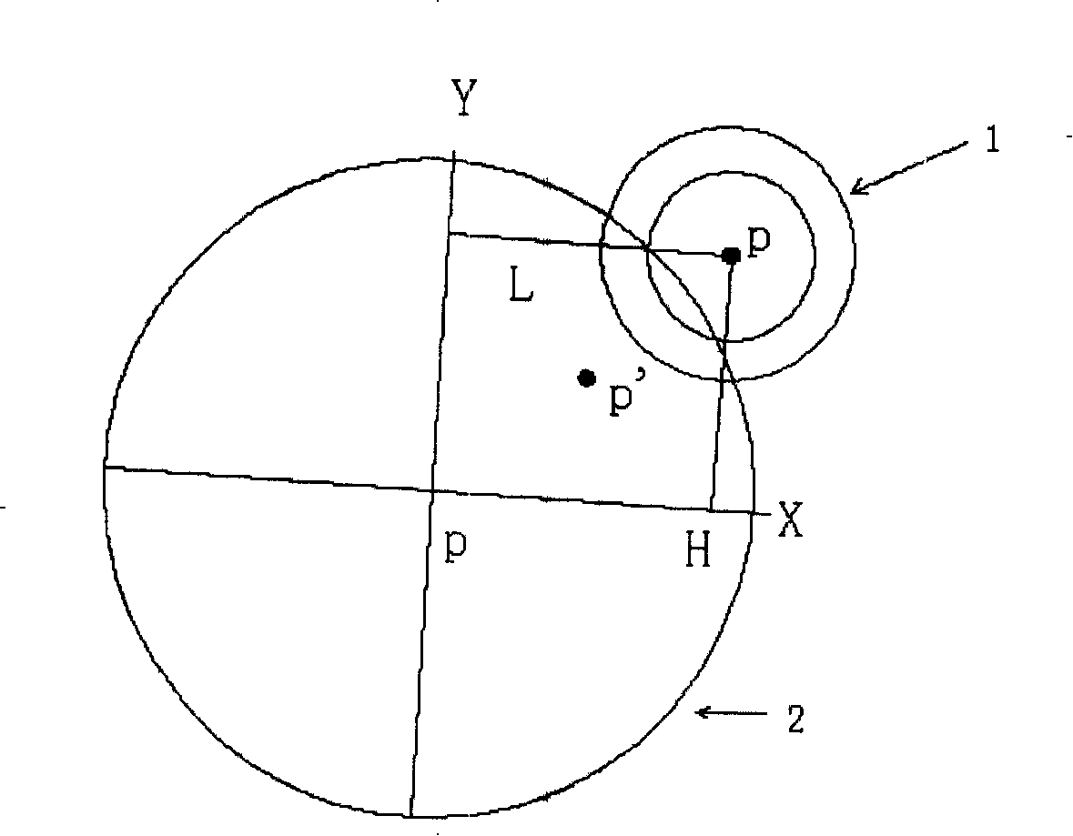
[0032] 2. Adjust the focal length of the optical plummet, see the reticle I clearly, and turn the two mutually perpendicular micro-movement spirals on the optical tube to make the intersection of the reticle I and the optical plummet separate. The reticle circle on the reticle conforms to figure 2 .

[0033] 3. Turn the light tube 180 degrees, lock the brake knob on the light tube, and observe the alignment between the reticle circle of the dot aligner and the axis of the reticle I. R...


PUM


Abstract

The invention provides a calibrator for an optical plummet and is a specialized equipment for the efficient examination and calibration of the optical plummet of an optical theodolite, an electric theodolite and a total station instrument of the surveying and mapping field in particular. The calibrator for the optical plummet is adopted to examine the optical plummet and then the offset value of the optical plummet can be determined for correction. The invention has simple, convenient and shortcut operation and reliable performance.

Description

Technical field: [0001] The invention relates to the technical field of surveying and mapping instruments. Including the inspection and correction of optical theodolite, electronic theodolite and optical plummet of total station. Background technique: [0002] At present, domestic and foreign instrument manufacturers and users generally adopt two methods for inspection and calibration of optical theodolite, electronic theodolite and total station optical plummet: [0003] 1. The collimator fixed correction method is to force the correction of the optical plummet to be inspected. This method is limited by the structure of the light pipe. When the reticle of the light pipe is changed by factors such as vibration, the optical plummet to be inspected cannot be corrected. Not universal. [0004] 2. The actual observation method needs to place the instrument on the tripod and operate according to the procedures of the instrument. The operator must have rich experience and stand ...

Claims


Application Information

Patent Timeline
Patent Type & Authority Applications(China)
IPC IPC(8): G01M11/00G01M11/02G01C1/00G01C25/00
Inventor 赵雷唐晓新
Owner 赵雷
Learn More