
Wire rope end connector fatigue test apparatus

A fatigue test and wire rope technology, applied in the direction of using repetitive force/pulse force to test the strength of materials, measuring devices, instruments, etc., can solve the problems of inability to adjust, long test time, low efficiency, etc., and achieve a wide range of applications and high efficiency. 、Convenient, fast and accurate data analysis and collection

Inactive Publication Date: 2008-05-21
TOSHIBA ELEVATOR KK
View PDF0 Cites 22 Cited by
  • Summary
  • Abstract
  • Description
  • Claims
  • Application Information

AI Technical Summary

Problems solved by technology

For the above-mentioned existing fatigue testing machine, there are the following deficiencies: (1) the cam 2 and the push plate 3 are not fixed, and only rely on the rotation of the cam 2 to drive and link, which is not suitable for high-frequency test conditions
Therefore, when the total number of tests is constant, the required test time is more
(2) One end of the spring 5 is fixed, that is figure 1 The middle L size is fixed and cannot be adjusted, which is not conducive to adjusting the initial test conditions of the specimen
(3) The fatigue test of two rope end joints can only be carried out at most at the same time, and the efficiency is not high
(4) Inertial impact and wear will occur between the cam and the push plate, which will affect the reliability and life of the fatigue testing machine

Method used


Image

  • Wire rope end connector fatigue test apparatus
  • Wire rope end connector fatigue test apparatus
  • Wire rope end connector fatigue test apparatus

Examples


Embodiment Construction

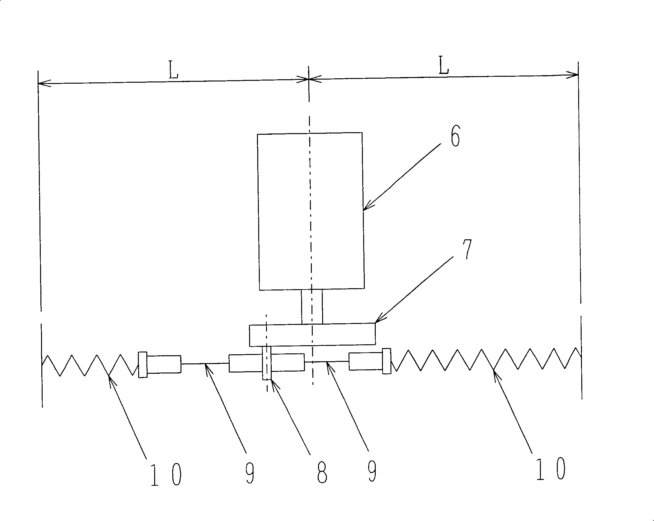
[0017] Such as figure 2 As shown in the schematic diagram, the fatigue testing machine according to the first embodiment of the present invention includes: a motor 6 used as a power mechanism, an eccentric wheel 7 used as a rotating mechanism, arranged on the eccentric wheel and connected to two rope ends respectively One end of the test piece 9 is fixedly connected to a connecting part 8, and two springs 10 are fixedly connected to the other end of the rope end joint test piece 9 through the connecting part. The connecting part 8 is fixed on the eccentric wheel 7 and deviates from the central axis of the eccentric wheel by a certain distance. Each rope end joint test piece 9 consists of two rope end joints and a wire rope between them. The other end of the spring 10 is connected with a fixed bracket. In addition, the connecting parts 8 for fixedly connecting the eccentric wheel 7 and two opposite rope end joints can be made of various forms such as bolts and nuts, bearings...


PUM


Abstract

The present invention provides a fatigue testing device for the rope end joint of a steel wire rope, which comprises a power mechanism, a rotary mechanism, a spring, a fixed bracket, a tensile force sensor, a counter, a temperature controller and a data collecting computer. In the present invention, one end of the rope end joint specimen is fixed on and connected with the rotary mechanism by a connecting component. The other end is connected with the spring. With the rotating of the rotary mechanism, when the spring is stretched, the extension length of the spring can change to and fro, so the specimen bears the continuous changing load. In the device of the present invention, the rotary mechanism can drive two groups of rope end joint specimens and springs. At most two groups, four rope end joints can be tested each time. The fatigue load test of the various specification of the steel wire rope end joint is satisfied. The present invention greatly improves the test ability and the use efficiency of the test device.

Description

technical field [0001] The invention relates to fatigue test equipment for a steel wire rope end joint device, in particular to a fatigue test equipment for a special steel wire rope end joint for elevators. The wire rope end joints can be of cold extruded structure, metal-filled conical sleeve structure, heart-shaped ring structure or wedge-shaped rope end sleeve and other structures. Background technique [0002] The existing steel rope end joint fatigue testing machine, the structure diagram is as follows figure 1 As shown, it mainly includes motor 1, cam 2, push plate 3, joint test piece 4, spring 5 and other components. Such as figure 1 As shown, during the fatigue test of the rope end joint, the motor 1 drives the cam 2 to rotate, and the cam 2 pushes the push plate 3, so that the push plate 3 reciprocates with the rotation of the cam 2, so the length of the spring 5 is also constantly changing. Thus, the specimen 4 is subjected to alternating loads. For the above-...

Claims


Application Information

Patent Timeline
IPC IPC(8): G01N3/34G01N19/00
Inventor 高石茂赵文刚
Owner TOSHIBA ELEVATOR KK
Learn More