Steel ball cold heading technique and steel ball cold header

A cold heading machine and cold heading technology, applied in the direction of manufacturing tools, metal processing equipment, forging/pressing/hammer devices, etc., can solve problems such as uneven distribution of stress and strain, low pass rate of steel ball blanks, folding, etc., and achieve stress The effect of uniform strain distribution, improvement of quality and pass rate, and reduction of production cost

Inactive Publication Date: 2008-05-28
JIANGNAN UNIV
View PDF0 Cites 21 Cited by
  • Summary
  • Abstract
  • Description
  • Claims
  • Application Information

AI Technical Summary

Problems solved by technology

[0003] In the process of using the existing steel ball blank production process and cold heading machine to produce steel ball blanks, due to the deformation of the bar during the shearing process, it cannot be guaranteed that the blank is a cylinder, and the blank will have burrs or burrs, so It will cause the blank to have poor plastic deformation and uneven distribution of stress and strain during the stamping and cold heading process, resulting in defects in the steel ball blank after stamping, such as partial lack of filling, material folding, etc., the pass rate of the steel ball blank is low, and the steel ball blank The quality of the ball blank is difficult to guarantee
In addition, it also causes uneven stress on the cold heading die during the stamping process, which affects the service life of the cold heading die

Method used


Image

  • Steel ball cold heading technique and steel ball cold header
  • Steel ball cold heading technique and steel ball cold header
  • Steel ball cold heading technique and steel ball cold header

Examples


Embodiment Construction

[0029] The specific implementation manners of the present invention will be further described in detail below in conjunction with the accompanying drawings.

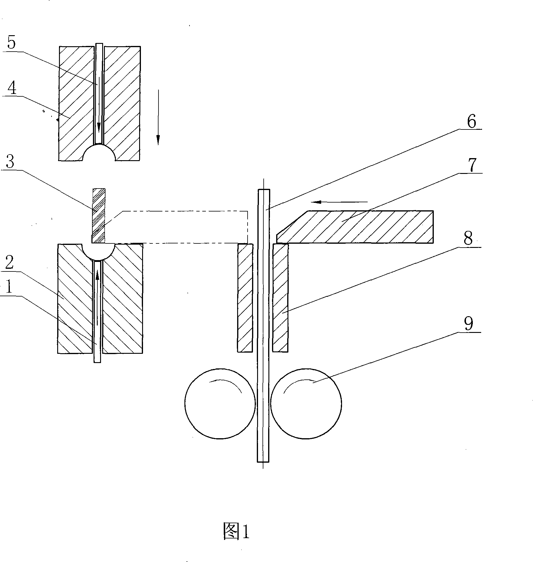
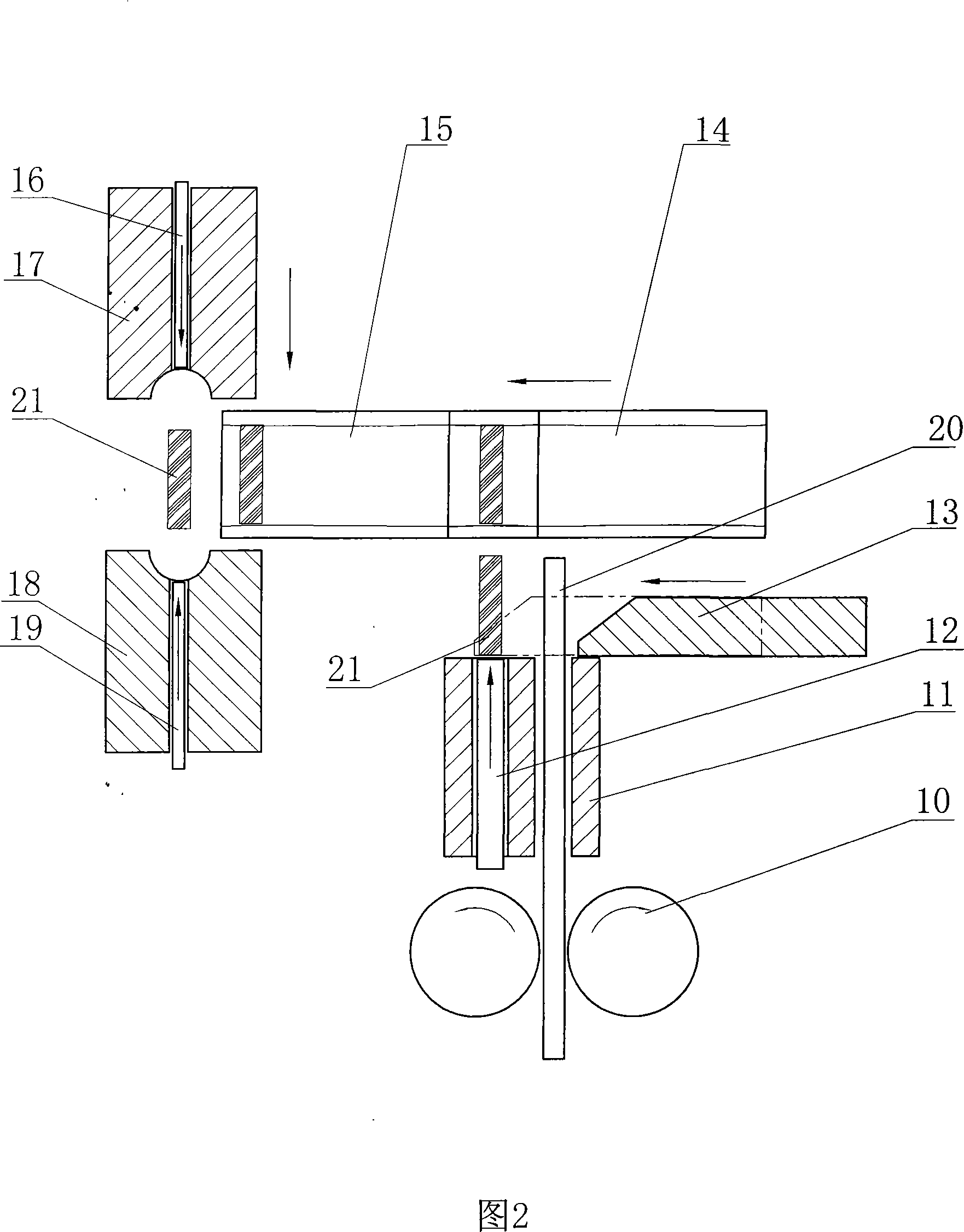
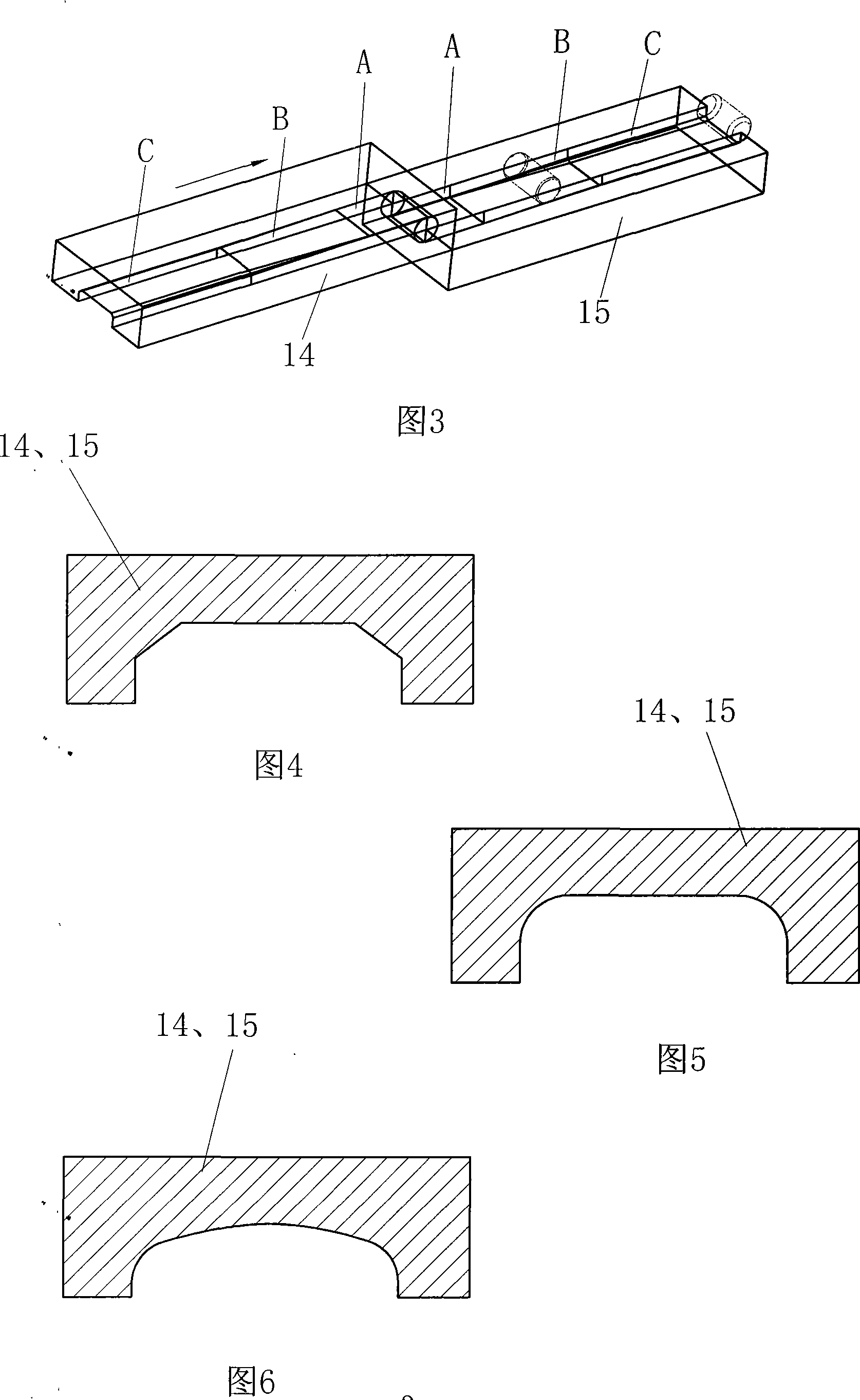
[0030] As shown in Figure 2, the feed runner 10 of the motor drives the feeding mechanism to send the bar 20 along the axial direction of the guide hole of the guide plate 11. After the bar stretches out to a certain length, the shearing die 13 of the shearing mechanism will The bar stock 20 is cut off, and the cut blank 21 is sent to the end face of the ejector rod 12 of the feeding mechanism, and the ejector rod 12 pushes the blank 21 into the inner cavity of the upper rubbing die 14 and the lower rubbing die 15 of the rubbing cutting mechanism At the position, the upper rubbing die 14 and the lower rubbing die 15 make relative movement to pre-deform the blank 21 in its cavity, and send the pre-deformed billet 21 to the cold heading die through the feeding mechanism (not shown in the figure) , the ejector pin 16 of the...


PUM


Abstract

The invention discloses a steel ball cold heading process and a relevant steel ball cold heading machine. The invention is characterized in that in the steel ball cold heading process, after barstocks are cut into column-shaped blanks, two ends of the column shaped blanks are rubbed and cut into inversed angel or round angle shapes, and then the blanks are transferred to a cold heading mechanism to be headed into steel ball rough cast; a blank rubbing and cutting mechanism is additionally arranged on the corresponding cold heading machine. The rubbing and cutting mechanism consists of an upper rubbing and cutting die and a lower rubbing and cutting die which are provided with formed notches respectively and carry out relative movement. As the rubbing and cutting machining to the blanks is added before the cold heading, the fact that the blanks entering the cold heading mechanism are the cylinders with round angles or inversed angles or the podetiums with other special shapes and no burrs are produced can be guaranteed, and the steel ball rough cast has better plastic transfiguring capability and uniform distribution of stress. The quality and eligibility rate of the steel ball rough cast can be enhanced and the manufacturing cost thereof can be reduced. Furthermore, as the shapes of the blanks entering the cold forging mechanism are regular, the stress born by the cold heading mechanism is equal in the punching process, thus the service life of cold heading dies is prolonged.

Description

technical field [0001] The invention relates to a steel ball manufacturing equipment and a related process, in particular to a steel ball cold heading machine and a corresponding steel ball cold heading process. Background technique [0002] Steel ball cold heading processing is a production process that provides steel ball blanks for steel ball grinding. The quality of steel ball cold heading processing directly affects the quality of steel ball finished products. The existing steel ball blank cold heading production process is: feeding (bar stock)→shearing→feeding (cylindrical blank)→cold heading (stamping)→steel ball blank. Its implementation process in the steel ball cold heading machine is as follows (as shown in Figure 1): the motor drives the feeding runner 9 to feed the bar 6 along the axial direction of the guide hole of the guide plate 8, and the bar 6 extends out to a certain length Finally, the shearing die 7 of the shearing mechanism cuts the bar 6 into a blank...

Claims


Application Information

Patent Timeline
Patent Type & Authority Applications(China)
IPC IPC(8): B21J5/02B21J1/02B21K27/02B21K27/06
Inventor 傅蔡安
Owner JIANGNAN UNIV
Why Eureka
Try Eureka