Machining unit

A technology for machine units and processing tools, which is applied in the direction of metal processing machinery parts, processing machines for manufacturing flat surfaces, metal processing equipment, etc., and can solve complex structures, limited power of processing units, limited speed of edge processing equipment and limited total production, etc. problem, to achieve the effect of reducing weight

Inactive Publication Date: 2015-07-08
BRANDT KANTENTECHNIK GMBH
View PDF11 Cites 0 Cited by
  • Summary
  • Abstract
  • Description
  • Claims
  • Application Information

AI Technical Summary

Problems solved by technology

Here it turns out that the power of the known processing units is limited and thus also the speed of travel and the total throughput of edge processing plants
Furthermore, the known milling units have a comparatively complex structure

Method used


Image

  • Machining unit
  • Machining unit

Examples


Embodiment Construction

[0017] Hereinafter, preferred embodiments of the present invention will be described in detail with reference to the accompanying drawings.

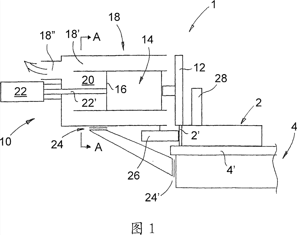
[0018] figure 1 A processing plant 1 as a preferred embodiment of the invention is shown schematically in side section. In this embodiment, the processing device is used for cutting and processing a workpiece 2, for example, the workpiece is at least partially made of wood, wood, plastic, etc., but the invention is not limited thereto. Precisely, in this exemplary embodiment, the processing device 1 is used for processing an edge 2' which is arranged on the narrow side of the workpiece 2 at the time and is glued there, for example. In addition, the workpiece 2 to be processed is transported in the processing device 1 in the direction of travel (perpendicular to figure 1 on the drawing surface), for example on the conveyor belt 4' or on the conveyor table.

[0019] Furthermore, as a preferred embodiment of the invention, the processing...


PUM


Abstract

The processing unit has a rotary machining tool (12), a rotary tool drive (14) with a housing (16) and a swarf collection hood (18) for swarf falling in the tool area with a through opening (20) into which the tool drive protrudes at least partly. The rotary drive housing is at least partly in sliding contact with the swarf collection hood in the through opening area. An independent claim is also included for a processing machine.

Description

technical field [0001] The invention relates to a machining unit according to the preamble of claim 1 , in particular for cutting edge regions of workpieces. Background technique [0002] Machining units of the above-mentioned type are used, for example, in the furniture industry for milling off the excess of glued edges so as to be flush with the workpiece surface. Thus, for example, DE 4030138C2 discloses a device for positioning and end milling edge strips. [0003] So-called profile milling units round off the corners of the edges glued to the workpiece on all sides, adapting the shape of the corners to the contour of the workpiece. It is also called bevel copying. This processing is done during the movement of the workpiece, that is, the workpiece has a speed in the conveying direction during processing. [0004] For profile milling units that process workpieces, this means that the milling head must move around the passing workpiece. Under the premise of as much po...

Claims


Application Information

Patent Timeline
Patent Type & Authority Patents(China)
IPC IPC(8): B27C1/00
CPCB27D5/006B23Q11/0046
Inventor 塞巴斯蒂安·洪德托马斯·诺佩
Owner BRANDT KANTENTECHNIK GMBH
Why Eureka
Try Eureka